Official TSB and Recall Thread
 06-21-2010, 04:49 PM
#141
Founding Member
Thread Starter

Join Date: 11-23-2007
Location: Texas
Posts: 8,210
10-08-50-007
#10-08-50-007: Information on Driver and/or Passenger Seat Concerns with Armrest Comfort, Angle Adjustment and Height - (Jun 17, 2010)
Subject: Information on Driver and/or Passenger Seat Concerns with Armrest Comfort, Angle Adjustment and Height
Models: 2007-2010 Chevrolet HHR
--------------------------------------------------------------------------------
Note: Do not replace the armrest for customer concerns of incorrect armrest angle or height. Installing a new armrest will not change the angle or height, and will not fix the customer concern.
Some customers may comment that the driver and/or passenger seat armrest is uncomfortable or that the armrest is tilting on a downward or upward angle or that the height of the armrests is not the same on both front seats.
The front driver and passenger seats are equipped with armrests that have been built into the seat back assembly. The angle of the armrests is determined by the angle of the seat back. The height of the armrest is determined by the height of the seat. Instruct the customer of the interaction of the seat back angle to the angle of the armrest, and the seat height to the height of the armrest. Reclining the seat back will raise the front of the armrest, adjusting the seat back to a more upright position will lower the front of the armrest. Raising the seat height will raise the armrest, and lowering the seat will lower the armrest.
These adjustments may cause the driver and passenger armrests to be at different heights and angles relative to one another.
It is recommended that dealership personnel demonstrate the seat adjustment functions to the customer. This will aid the customer in finding suitable seat position.
 06-21-2010, 04:53 PM
#142
Founding Member
Thread Starter
Join Date: 11-23-2007
Location: Texas
Posts: 8,210
06-02-32-002d
#06-02-32-002D: Information for Normal Operating Characteristics of Electric Power Steering (EPS) System During Extended Lock-to-Lock Turns or When Held at Maximum Steering Wheel Rotation and/or DTCs C0176 and C0476 - (Jun 17, 2010)
Subject: Information for Normal Operating Characteristics of Electric Power Steering (EPS) System During Extended Lock-to-Lock Turns or When Held at Maximum Steering Wheel Rotation and/or DTCs C0176 and C0476 Set
Models: 2004-2011 Chevrolet Malibu, Malibu Maxx
2005-2011 Chevrolet Cobalt, Equinox
2006-2011 Chevrolet HHR
2010-2011 GMC Terrain
2005-2010 Pontiac G6
2005-2006 Pontiac Pursuit (Canada Only)
2006-2009 Pontiac Torrent
2007-2010 Pontiac G5
2002-2009 Saturn VUE
2003-2007 Saturn ION
2007-2009 Saturn AURA
Equipped With Electric Power Steering (EPS) Only
--------------------------------------------------------------------------------
This bulletin is being revised to add model years and clarify the information. Please discard Corporate Bulletin Number 06-02-32-002C (Section 02 - Steering).
--------------------------------------------------------------------------------
� The purpose of this bulletin is to inform technicians of the normal operating characteristics of the electric power steering system (EPS) when the steering wheel is turned in either direction or held at maximum rotation for an extended period of time.
� When the steering wheel is cycled repeatedly or turned to its maximum rotation, the power steering control module (PSCM) will command the maximum amount of current to the EPS motor. If the steering wheel is held in this position for an extended period of time, the PSCM will go into overload protection mode to avoid system thermal damage. In this mode, the PSCM will limit the amount of current commanded to the EPS motor, which will reduce the power steering assist level.
� If the PSCM detects a high system temperature and the overload protection mode is initiated, DTC C0176 System Thermal Error may set. On some models, DTC C0476 Electric Steering Motor Circuit Range/Performance may also set. These DTCs indicate normal PSCM action, to reduce the steering assist in order to prevent thermal damage to power steering system components.
� Refer to Power Steering System Description and Operation in SI or the appropriate Service Manual for more information about this and other vehicle-specific information on electric power steering systems.
� For customer inquiries regarding this characteristic, please guide the customer to the Steering section under Driving Your Vehicle in their vehicle Owner Manual. This information is reproduced below for quick reference.
Owner Manual Information
If you turn the steering wheel in either direction several times until it stops, or hold the steering wheel in the stopped position for an extended amount of time, you may notice a reduced amount of power steering assist. The normal amount of power steering assist should return shortly after a few normal steering movements.
06-23-2010, 08:23 AM
#143
Founding Member
Thread Starter
Join Date: 11-23-2007
Location: Texas
Posts: 8,210
Pi0160
#PI0160: Unable to Open Hood, Inside Hood Latch Release Cable Inoperative (Reattach Hood Release Cable) - (Jun 22, 2010)
Subject: Unable to Open Hood, Inside Hood Latch Release Cable Inoperative (Reattach Hood Release Cable)
Models: 2010 Chevrolet HHR
--------------------------------------------------------------------------------
Condition/Concern
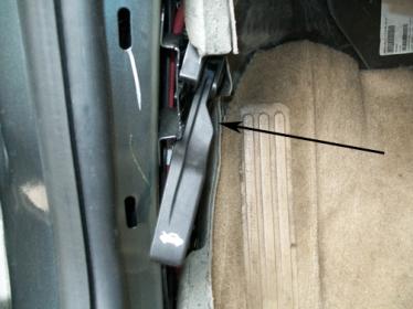
Some customers may comment that they are unable to open the hood, the hood release cable is not fully seated in the hood release handle or the release handle is not secured to the mounting bracket. There are also instances that, over time and use, some of these cables can become detached from the handle or the handle becomes loose.
Recommendation/Instructions
Important: DO NOT replace the hood latch cable release assembly.
Snap the release cable end to the handle back in place and secure the handle to the mounting bracket.
Subject: Unable to Open Hood, Inside Hood Latch Release Cable Inoperative (Reattach Hood Release Cable)
Models: 2010 Chevrolet HHR
--------------------------------------------------------------------------------
Condition/Concern
Some customers may comment that they are unable to open the hood, the hood release cable is not fully seated in the hood release handle or the release handle is not secured to the mounting bracket. There are also instances that, over time and use, some of these cables can become detached from the handle or the handle becomes loose.
Recommendation/Instructions
Important: DO NOT replace the hood latch cable release assembly.
Snap the release cable end to the handle back in place and secure the handle to the mounting bracket.
06-23-2010, 08:27 AM
#144
Founding Member
Thread Starter
Join Date: 11-23-2007
Location: Texas
Posts: 8,210
Pi0158
#PI0158: Intermittent Tapping or Clunk Noise from Rear at Low to Moderate Speeds During Light to Moderate Brake Apply (Refinish Rear Brake Drums) - (Jun 21, 2010)
Subject: Intermittent Tapping or Clunk Noise from Rear at Low to Moderate Speeds During Light to Moderate Brake Apply (Refinish Rear Brake Drums)
Models: 2010 Chevrolet HHR
--------------------------------------------------------------------------------
The following procedure may be helpful if the vehicle exhibits the symptoms described in this PI.
Condition/Concern
� Some customers may comment on an intermittent tapping noise coming from the rear of the vehicle upon applying the brakes when driving between 35-40 mph (56-64 km/h).
� They may also comment on an intermittent clunk noise coming from the rear of the vehicle during a light to moderate brake apply at speeds of 10 mph (16 km/h) or less.
� These conditions may be caused by brake drums that are out of round.
Recommendation/Instructions
Important: DO NOT replace the brake drums. Refinish both of the brake drums.
Test drive the vehicle and verify that the above condition or conditions exist as described.
⇒ If either condition exists as described, proceed to Step 2.
Raise and support the vehicle. Refer to Lifting and Jacking the Vehicle in SI.
Remove both tire and wheel assemblies. Refer to Tire and Wheel Removal and Installation in SI.
Warning: Refer to Brake Dust Warning in the Preface section in SI.
Remove the brake drums. Refer to Brake Drum Replacement in SI.
Refinish the brake drums. Refer to Brake Drum Refinishing in SI.
Note: Failure to clean any existing corrosion from the wheel hub flange mating surface may result in increased lateral runout of the brake drum and brake system pulsation.
Clean the wheel hub flange mating surface of any corrosion.
Install the brake drums. Refer to Brake Drum Replacement in SI.
Install the tire and wheel assemblies. Refer to Tire and Wheel Removal and Installation in SI.
Lower the vehicle.
Test drive the vehicle and verify that the concern has been corrected.
06-23-2010, 08:36 AM
#145
Founding Member
Thread Starter
Join Date: 11-23-2007
Location: Texas
Posts: 8,210
Pic5356a
#PIC5356A: AC Compressor Will Not Engage - AC Pressure In The ECM Data Reads 0 PSI - No DTCs - (Jun 22, 2010)
Subject: AC Compressor Will Not Engage AC Pressure in the ECM Data Reads 0 PSI No DTC's
Models: 2008-2010 Chevrolet Cobalt
2008-2010 Pontiac G5
2008-2011 Chevrolet HHR
Equipped with RPO C60 or C67
--------------------------------------------------------------------------------
This PI was superseded to update models. Please discard PIC5356.
--------------------------------------------------------------------------------
The following diagnosis might be helpful if the vehicle exhibits the symptom(s) described in this PI.
Condition/Concern:
A customer may comment that their AC is inoperative. Upon diagnosis the technician will find the AC compressor will not engage and there are no codes stored. The technician may find the scan tool ECM data indicates No for the AC Request and AC Relay Command, and the AC Pressure Sensor value is 0 psi. No codes are setting current or history. This concern could be caused by incorrect BCM Setup during a previous repair.
Recommendation/Instructions:
Attempt to enable the AC option in the BCM. If the option is not listed, replace the BCM. Use caution when setting up the BCM to ensure all the correct vehicle options are selected. Some of the options only appear during the initial BCM Setup procedure.
06-25-2010, 11:09 AM
#146
Founding Member
Thread Starter
Join Date: 11-23-2007
Location: Texas
Posts: 8,210
02-08-42-001d
#02-08-42-001D: Headlamp Lens Overheating When Covered and Chemical Damage to Exterior Polycarbonate Headlamp Lenses - (Jun 21, 2010)
Subject: Headlamp Lens Overheating When Covered and Chemical Damage to Exterior Polycarbonate Headlamp Lenses
Models: 2011 and Prior GM Passenger Cars and Trucks (Including Saturn)
2010 and Prior HUMMER H2, H3
2009 and Prior Saab 9-7X
--------------------------------------------------------------------------------
This bulletin is being revised to add model years and to revise the warning statements. Please discard Corporate Bulletin Number 02-08-42-001C (Section 08 - Body and Accessories).
--------------------------------------------------------------------------------
The bulletin is being issued to make dealers and customers aware of chemical damage that may be caused to exterior polycarbonate headlamp lenses. Most late model vehicles have these types of headlamp lenses. This material is used because of its temperature and high impact resistance.
A variety of chemicals can cause crazing or cracking of the headlamp lens. Headlamp lenses are very sensitive. Care should be exercised to avoid contact with all exterior headlamp lenses when treating a vehicle with any type of chemical, such as those recommended for rail dust removal. Rubbing compound, grease tar and oil removers, tire cleaners, cleaner waxes and even car wash soaps in too high a concentration may also attribute to this condition. This could result in the need to replace the entire headlamp housing.
Warning: Use only lukewarm or cold water, a soft cloth and a car washing soap to clean exterior lamps and lenses.
Also, crazing or deformations of the lens may occur if a shop mat or fender cover is draped over the fender and covers a portion or all of the headlamp assembly while the DRL or headlamps are on. This action restricts the amount of heat dissipated by the headlamps.
Warning: Care should be taken to not cover headlamps with shop mats or fender covers if the vehicle is being serviced with the headlamps or DRL illuminated. Covering an illuminated lamp can cause excessive heat build up and crazing/deformation of the lens may occur. The degradation of the lens can be unnoticeable at first and eventually become hairline cracks in the lens. In extreme cases, it could cause the lens to deform. This damage can also be caused by aftermarket shields that are often tinted in color.
Once a heat buildup is generated by the headlamp, a degradation of the headlamp lens begins. This degradation of the lens can be unnoticeable at first and eventually manifest as spider cracks. In more extreme cases, it will begin to melt the lens of the headlamp.
Notice: Headlamps damaged by chemicals, improper cleaning, or overheating due to being covered are not covered under the new vehicle warranty.
06-25-2010, 11:12 AM
#147
Founding Member
Thread Starter
Join Date: 11-23-2007
Location: Texas
Posts: 8,210
99-09-40-005f
#99-09-40-005F: Seat Belt Extender Availability - (Jun 23, 2010)
Subject: Seat Belt Extender Availability
Models: 2011 and Prior GM Passenger Cars and Trucks (Including Saturn)
2009 and Prior HUMMER H2
2010 and Prior HUMMER H3
2005-2009 Saab 9-7X
--------------------------------------------------------------------------------
This bulletin is being revised to add the 2009-2011 model years and update the Warranty Information. Please discard Corporate Bulletin Number 99-09-40-005E (Section 09 - Restraints).
--------------------------------------------------------------------------------
Important: DO NOT use belt extenders when securing a child restraint.
The seat and shoulder belt restraint systems used in all General Motors vehicles have sufficient belt length to accommodate most drivers and passengers. Consequently, requests for belt extensions (extenders) should be minimal.
Seat belt extenders are available ONLY IN BLACK for most GM passenger cars and trucks produced in recent years. They are available in two different lengths, 23 cm (9 in) and 38 cm (15 in). They are designed to be coupled with the existing belts in each vehicle. When in use, the extender makes the belt arrangement a "custom fit" and use by anyone else or in another vehicle will lessen or nullify the protection offered by the vehicle's restraint system. For this reason, it is extremely important that the correct length extender be used for the vehicle and occupant intended.
Important: Do not use an extender just to make it easier to buckle the safety belt. Use an extender only when you cannot buckle the safety belt without using an extender.
Parts Information
Contact GM Parts.
Warranty Information
� Seat belt extenders are a NO CHARGE item to all GM customers who request them for their specific vehicles.
� Dealers should not be charging part costs since these extenders are supplied by GM to the dealers.
� Dealers should not be charging labor costs since the extender can be customer installed.
06-25-2010, 11:13 AM
#148
Founding Member
Thread Starter
Join Date: 11-23-2007
Location: Texas
Posts: 8,210
10-08-50-007
#10-08-50-007: Information on Driver and/or Passenger Seat Concerns with Armrest Comfort, Angle Adjustment and Height - (Jun 17, 2010)
Subject: Information on Driver and/or Passenger Seat Concerns with Armrest Comfort, Angle Adjustment and Height
Models: 2007-2010 Chevrolet HHR
--------------------------------------------------------------------------------
Note: Do not replace the armrest for customer concerns of incorrect armrest angle or height. Installing a new armrest will not change the angle or height, and will not fix the customer concern.
Some customers may comment that the driver and/or passenger seat armrest is uncomfortable or that the armrest is tilting on a downward or upward angle or that the height of the armrests is not the same on both front seats.
The front driver and passenger seats are equipped with armrests that have been built into the seat back assembly. The angle of the armrests is determined by the angle of the seat back. The height of the armrest is determined by the height of the seat. Instruct the customer of the interaction of the seat back angle to the angle of the armrest, and the seat height to the height of the armrest. Reclining the seat back will raise the front of the armrest, adjusting the seat back to a more upright position will lower the front of the armrest. Raising the seat height will raise the armrest, and lowering the seat will lower the armrest.
These adjustments may cause the driver and passenger armrests to be at different heights and angles relative to one another.
It is recommended that dealership personnel demonstrate the seat adjustment functions to the customer. This will aid the customer in finding suitable seat position.
Subject: Information on Driver and/or Passenger Seat Concerns with Armrest Comfort, Angle Adjustment and Height
Models: 2007-2010 Chevrolet HHR
--------------------------------------------------------------------------------
Note: Do not replace the armrest for customer concerns of incorrect armrest angle or height. Installing a new armrest will not change the angle or height, and will not fix the customer concern.
Some customers may comment that the driver and/or passenger seat armrest is uncomfortable or that the armrest is tilting on a downward or upward angle or that the height of the armrests is not the same on both front seats.
The front driver and passenger seats are equipped with armrests that have been built into the seat back assembly. The angle of the armrests is determined by the angle of the seat back. The height of the armrest is determined by the height of the seat. Instruct the customer of the interaction of the seat back angle to the angle of the armrest, and the seat height to the height of the armrest. Reclining the seat back will raise the front of the armrest, adjusting the seat back to a more upright position will lower the front of the armrest. Raising the seat height will raise the armrest, and lowering the seat will lower the armrest.
These adjustments may cause the driver and passenger armrests to be at different heights and angles relative to one another.
It is recommended that dealership personnel demonstrate the seat adjustment functions to the customer. This will aid the customer in finding suitable seat position.
06-25-2010, 12:01 PM
#149
Founding Member
Thread Starter
Join Date: 11-23-2007
Location: Texas
Posts: 8,210
xTooltipElement
Service Information
Document ID: 2491676
--------------------------------------------------------------------------------
#PIP4453A: No ISS Signal At Low Speeds - (Jun 17, 2010)
Subject: No ISS Signal at Low Speeds
Models: 2007-2010 Chevrolet Cobalt, Malibu, HHR
2007-2010 Pontiac G5, G6
2007-2009 Saturn Aura, Ion, Vue
equipped with 4T45E transmission (RPOs MN5, ME7)
--------------------------------------------------------------------------------
This PI was superseded to update model years and condition. Please discard PIP4453.
-------------------------------------------------------------------------------
The following diagnosis might be helpful if the vehicle exhibits the symptom(s) described in this PI.
Condition/Concern:
Recently several cases have surfaced where DTC P0717 sets and there is no ISS signal until 5 mph or 1000-1200 rpm.
Recommendation/Instructions:
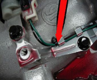
If the air gap and resistance checks are ok, but concern continues, the cause may be the internal trans wiring harness has been chaffed by a sharp edge on a hold down clip and is grounding out until sufficient vibration at higher RPM's interrupts the ground out. Checking 20 Way Connector pins 'S' and 'V' to ground may show some resistance readings when there should be none. For this condition (no ISS until higher RPM), replace the transmission internal wiring harness. This applies to both RPO's: MN5, ME7.
For pin out locations see SI Doc 1887360, connector #11 (engine to transmission).
Service Information
Document ID: 2491676
--------------------------------------------------------------------------------
#PIP4453A: No ISS Signal At Low Speeds - (Jun 17, 2010)
Subject: No ISS Signal at Low Speeds
Models: 2007-2010 Chevrolet Cobalt, Malibu, HHR
2007-2010 Pontiac G5, G6
2007-2009 Saturn Aura, Ion, Vue
equipped with 4T45E transmission (RPOs MN5, ME7)
--------------------------------------------------------------------------------
This PI was superseded to update model years and condition. Please discard PIP4453.
-------------------------------------------------------------------------------
The following diagnosis might be helpful if the vehicle exhibits the symptom(s) described in this PI.
Condition/Concern:
Recently several cases have surfaced where DTC P0717 sets and there is no ISS signal until 5 mph or 1000-1200 rpm.
Recommendation/Instructions:
If the air gap and resistance checks are ok, but concern continues, the cause may be the internal trans wiring harness has been chaffed by a sharp edge on a hold down clip and is grounding out until sufficient vibration at higher RPM's interrupts the ground out. Checking 20 Way Connector pins 'S' and 'V' to ground may show some resistance readings when there should be none. For this condition (no ISS until higher RPM), replace the transmission internal wiring harness. This applies to both RPO's: MN5, ME7.
For pin out locations see SI Doc 1887360, connector #11 (engine to transmission).
07-20-2010, 03:27 PM
#150
Founding Member
Thread Starter
Join Date: 11-23-2007
Location: Texas
Posts: 8,210
Pi0178
#PI0178: Front Door Power Locks Will Not Unlock with Key Fob or Switch (Revise Lock Rod Anti-Rattle Foam) - (Jul 16, 2010)
Subject: Front Door Power Locks Won't Unlock with Key FOB or Switch (Revise Lock Rod Anti-Rattle Foam)
Models: 2009-2010 Chevrolet HHR
--------------------------------------------------------------------------------
Note: For vehicles built before 8/17/2009, refer to Corporate Bulletin Number 09-08-64-029 for other possible causes.
Condition/Concern
Some customers may comment that the front door power lock(s) fails to unlock when using the key FOB or the interior mounted power door lock switch. The door lock knob does actuate using the power door lock, but fails to unlock the latch. The doors will unlock using the manual lock knob when it is pulled up to the unlock position. This condition may be present on both the left and/or right front doors.
This condition may be caused by friction between the lock rod anti-rattle foam, located on the door trim, and the lock rod. This friction may cause the lock rod to bind and prevent power actuation of the lock.
Recommendation/Instructions
Important: DO NOT replace the front side door trim panel, door lock actuator or door lock rod to correct this condition.
Use the following procedure to revise the lock rod anti-rattle foam to prevent future binding.
Remove the affected door trim panel. Refer to Front Side Door Trim Panel Replacement in SI.
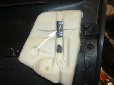
Locate the lock rod anti-rattle foam.
Remove the anti-rattle foam by pulling the foam off of the trim panel. Use care to not tear the anti-rattle foam.
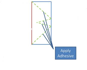
Using a pair of sharp scissors, cut the anti-rattle foam as shown in the graphic. Cut along the dotted green line to create the correct shape.
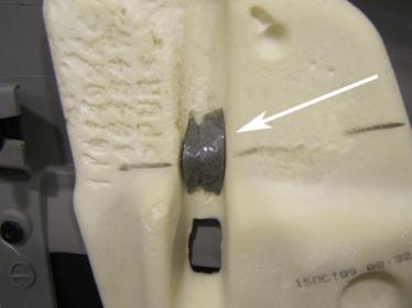
Apply spray trim adhesive, such as 3M� General Trim Adhesive Clear, Part # 051135-08088* or the equivalent, to the anti-rattle foam as shown. Use care to not get adhesive on the mylar anti-friction surface of the anti-rattle foam.
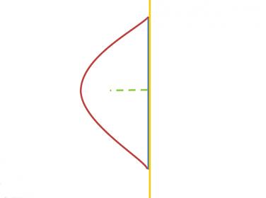
Close the opening in the anti-rattle foam to create the shape shown in the graphic.
Reinstall the anti-rattle foam in the original location on the door trim panel.
Reinstall the door trim panel. Refer to Front Side Door Trim Panel Replacement in SI.
Verify the function of the power door locks.
*We believe this source and their products to be reliable. There may be additional manufacturers of such products/materials. General Motors does not endorse, indicate any preference for, or assume any responsibility for the products or material from this firm or for any such items that may be available from other sources.
Parts Information
3M products may be purchased through your local distributor. Information about 3M product retailers in your area may be obtained by calling 1-866-364-3577 (U.S. and Canada).
Subject: Front Door Power Locks Won't Unlock with Key FOB or Switch (Revise Lock Rod Anti-Rattle Foam)
Models: 2009-2010 Chevrolet HHR
--------------------------------------------------------------------------------
Note: For vehicles built before 8/17/2009, refer to Corporate Bulletin Number 09-08-64-029 for other possible causes.
Condition/Concern
Some customers may comment that the front door power lock(s) fails to unlock when using the key FOB or the interior mounted power door lock switch. The door lock knob does actuate using the power door lock, but fails to unlock the latch. The doors will unlock using the manual lock knob when it is pulled up to the unlock position. This condition may be present on both the left and/or right front doors.
This condition may be caused by friction between the lock rod anti-rattle foam, located on the door trim, and the lock rod. This friction may cause the lock rod to bind and prevent power actuation of the lock.
Recommendation/Instructions
Important: DO NOT replace the front side door trim panel, door lock actuator or door lock rod to correct this condition.
Use the following procedure to revise the lock rod anti-rattle foam to prevent future binding.
Remove the affected door trim panel. Refer to Front Side Door Trim Panel Replacement in SI.
Locate the lock rod anti-rattle foam.
Remove the anti-rattle foam by pulling the foam off of the trim panel. Use care to not tear the anti-rattle foam.
Using a pair of sharp scissors, cut the anti-rattle foam as shown in the graphic. Cut along the dotted green line to create the correct shape.
Apply spray trim adhesive, such as 3M� General Trim Adhesive Clear, Part # 051135-08088* or the equivalent, to the anti-rattle foam as shown. Use care to not get adhesive on the mylar anti-friction surface of the anti-rattle foam.
Close the opening in the anti-rattle foam to create the shape shown in the graphic.
Reinstall the anti-rattle foam in the original location on the door trim panel.
Reinstall the door trim panel. Refer to Front Side Door Trim Panel Replacement in SI.
Verify the function of the power door locks.
*We believe this source and their products to be reliable. There may be additional manufacturers of such products/materials. General Motors does not endorse, indicate any preference for, or assume any responsibility for the products or material from this firm or for any such items that may be available from other sources.
Parts Information
3M products may be purchased through your local distributor. Information about 3M product retailers in your area may be obtained by calling 1-866-364-3577 (U.S. and Canada).