Official TSB and Recall Thread
 06-15-2009, 09:12 AM
#81
Founding Member
Thread Starter

Join Date: 11-23-2007
Location: Texas
Posts: 8,210
09-07-29-003
#09-07-29-003: Transmission Fluid Leak, Slipping Clutch or Broken Axle Shaft (Replace Trans Assembly/Front/Rear Mounts and Both Axle Shafts-Contact District Svc Mgr (Warranty Mgr in Canada) for Repair Approval) - (Jun 12, 2009)
Subject: Transmission Fluid Leak Due to Clutch Housing Fatigue, Slipping Clutch or Broken Axle Shaft (Contact District Service Manager/Warranty Manager (in Canada) for Repair Approval)
Models: 2005-2009 Chevrolet Cobalt SS
2008-2009 Chevrolet HHR SS
2004-2007 Saturn ION Redline
Equipped with 5-Speed Manual Transmission (RPO MU3)
Built Prior to February 12, 2009 (Lordstown) or February 26, 2009 (Ramos)
Attention: Be advised that failures of this nature are generally caused by customer abuse. They are NOT defects in materials or workmanship for which General Motors would be responsible for and should not be covered under the terms of the new vehicle warranty. Vehicles with this complaint should be inspected by your service manager and District Service Manager (Warranty Manager in Canada). A field product report should be submitted on each case. Also, if aftermarket kits are added that may effect the driveline loads, the transmission would not be warranted.
--------------------------------------------------------------------------------
Condition
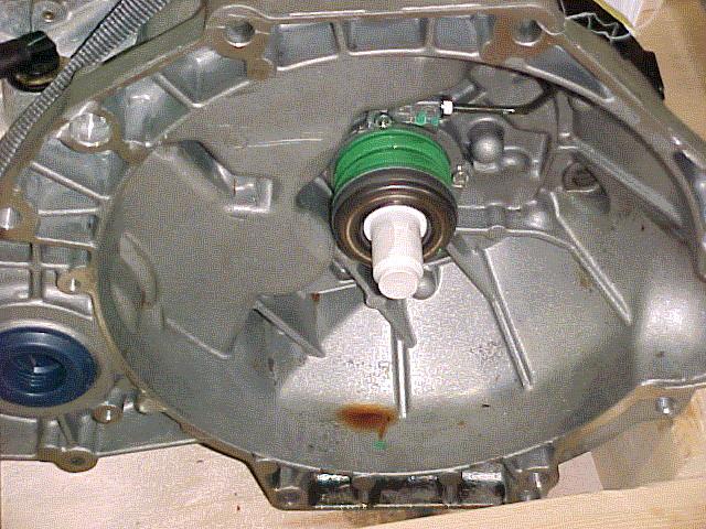
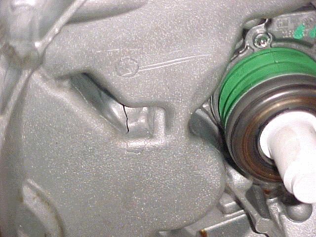
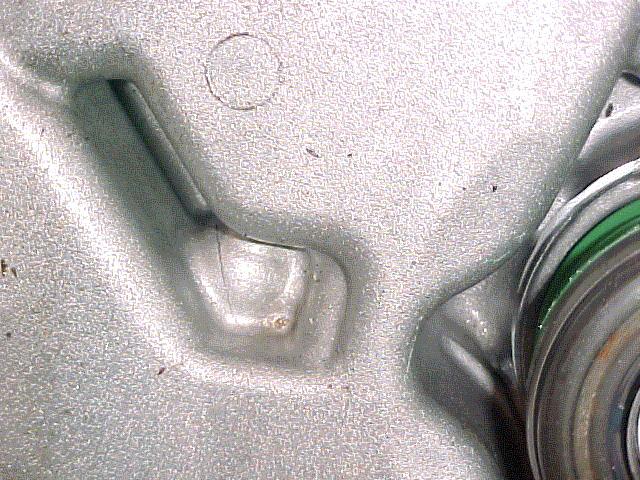
Some customers may comment about a slipping clutch. Upon further investigation, the technician will find transmission oil in the clutch housing.
Cause
This condition may be caused by excessive front wheel hop during wide open throttle (WOT) acceleration events. Excessive wheel hop transmits a torsional shock load into the transmission case. This may cause the transmission case to fracture (as shown in graphic below) and transmission fluid to leak into the clutch housing.
Correction
Important: Prior to any work being performed, contact your District Service Manager/Warranty Manager for repair approval.
For 2005-2007 Chevrolet Cobalt SS and 2004-2007 Saturn ION Redline
If this repair is approved by the District Service Manager/Warranty Manager, replace the transmission assembly. During removal of the transmission, replace the front (GM P/N 20814994) and rear (GM P/N 20814995) powertrain mounts. Refer to SI for the procedures on replacing the transmission front and rear mounts.
For 2008-2009 Chevrolet Cobalt SS and 2008-2009 Chevrolet HHR SS
If this repair is approved by the District Service Manager/Warranty Manager, replace the transmission assembly. During removal of the transmission, inspect the following parts and replace if necessary (excluding tires):
� Tire wear (excessive or uneven) front vs. rear or rubber debris in the front wheel house liner area.
� Inspect the upper right side mount for fluid leaks or (rubber) structural failure.
� Front and rear powertrain mounts, if necessary (refer to SI for the procedure on replacing the transmission front and rear mounts).
Important: Verify that the 12-volt battery has a battery charge of 12 to 16 volts. The battery must be able to maintain a charge during programming. Only use approved Midtronics 165-PCS charger or equivalent to maintain proper battery voltage during programming. The J 2534 MDI will reprogram the modules in less time than the Tech 2� scan tool.
Reprogram the ABS with a updated service calibration using the TIS2WEB Service Programming System (SPS) application. Make sure your Tech 2� is updated with the latest software version. The ABS calibration is available to dealerships in TIS2WEB (website version of TIS). Refer to Electronic Brake and/or Traction Control Module Reprogramming with SPS procedure in SI.
Install Clutch Actuator Pipe Elbow Assembly (P/N 24252286)
Disconnect the negative battery cable. Refer to Battery Negative Cable Disconnection and Connection.
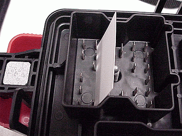
Remove the cover from the underhood electrical center.
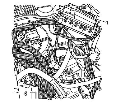
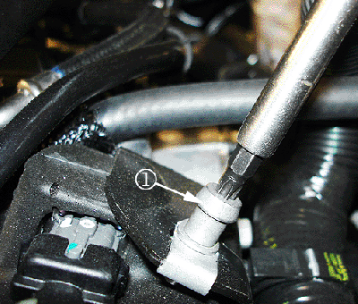
Remove the underhood electrical center bracket from the vehicle and reposition the electrical center (1) to access the bracket. Refer to Underhood Electrical Center or Junction Block Bracket Replacement.
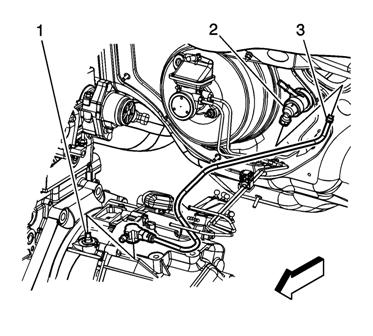
Note: Rotate the hose to stop brake fluid from running out of it.
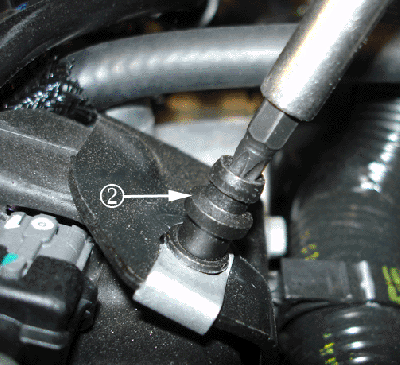
Disconnect the hydraulic clutch hose (3) from the clutch actuator cylinder (2) and the clutch master cylinder (1).
Install the clutch actuator pipe elbow assembly, GM P/N 24252286.
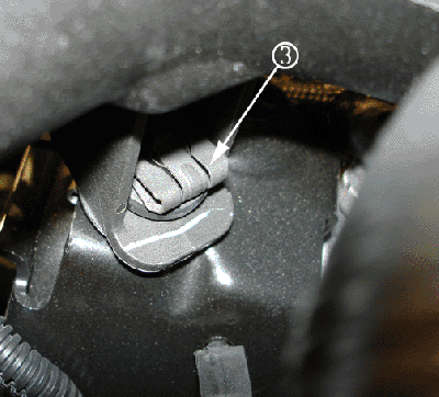
Connect the hydraulic clutch hose (3) to the clutch actuator cylinder (2).
Bleed the clutch hydraulic system. Refer to Hydraulic Clutch Bleeding.
Install the underhood electrical center bracket to the vehicle and install the electrical center into position on the bracket. Refer to Underhood Electrical Center or Junction Block Bracket Replacement.
Connect the negative battery cable. Refer to Battery Negative Cable Disconnection and Connection.
Parts Information
Part Number Description Qty
24252286 Elbow Asm - Clu Actr Cyl Pipe 1
20814994 (Front) Transmission Mount 1
20814995 (Rear) Transmission Mount 1
Subject: Transmission Fluid Leak Due to Clutch Housing Fatigue, Slipping Clutch or Broken Axle Shaft (Contact District Service Manager/Warranty Manager (in Canada) for Repair Approval)
Models: 2005-2009 Chevrolet Cobalt SS
2008-2009 Chevrolet HHR SS
2004-2007 Saturn ION Redline
Equipped with 5-Speed Manual Transmission (RPO MU3)
Built Prior to February 12, 2009 (Lordstown) or February 26, 2009 (Ramos)
Attention: Be advised that failures of this nature are generally caused by customer abuse. They are NOT defects in materials or workmanship for which General Motors would be responsible for and should not be covered under the terms of the new vehicle warranty. Vehicles with this complaint should be inspected by your service manager and District Service Manager (Warranty Manager in Canada). A field product report should be submitted on each case. Also, if aftermarket kits are added that may effect the driveline loads, the transmission would not be warranted.
--------------------------------------------------------------------------------
Condition
Some customers may comment about a slipping clutch. Upon further investigation, the technician will find transmission oil in the clutch housing.
Cause
This condition may be caused by excessive front wheel hop during wide open throttle (WOT) acceleration events. Excessive wheel hop transmits a torsional shock load into the transmission case. This may cause the transmission case to fracture (as shown in graphic below) and transmission fluid to leak into the clutch housing.
Correction
Important: Prior to any work being performed, contact your District Service Manager/Warranty Manager for repair approval.
For 2005-2007 Chevrolet Cobalt SS and 2004-2007 Saturn ION Redline
If this repair is approved by the District Service Manager/Warranty Manager, replace the transmission assembly. During removal of the transmission, replace the front (GM P/N 20814994) and rear (GM P/N 20814995) powertrain mounts. Refer to SI for the procedures on replacing the transmission front and rear mounts.
For 2008-2009 Chevrolet Cobalt SS and 2008-2009 Chevrolet HHR SS
If this repair is approved by the District Service Manager/Warranty Manager, replace the transmission assembly. During removal of the transmission, inspect the following parts and replace if necessary (excluding tires):
� Tire wear (excessive or uneven) front vs. rear or rubber debris in the front wheel house liner area.
� Inspect the upper right side mount for fluid leaks or (rubber) structural failure.
� Front and rear powertrain mounts, if necessary (refer to SI for the procedure on replacing the transmission front and rear mounts).
Important: Verify that the 12-volt battery has a battery charge of 12 to 16 volts. The battery must be able to maintain a charge during programming. Only use approved Midtronics 165-PCS charger or equivalent to maintain proper battery voltage during programming. The J 2534 MDI will reprogram the modules in less time than the Tech 2� scan tool.
Reprogram the ABS with a updated service calibration using the TIS2WEB Service Programming System (SPS) application. Make sure your Tech 2� is updated with the latest software version. The ABS calibration is available to dealerships in TIS2WEB (website version of TIS). Refer to Electronic Brake and/or Traction Control Module Reprogramming with SPS procedure in SI.
Install Clutch Actuator Pipe Elbow Assembly (P/N 24252286)
Disconnect the negative battery cable. Refer to Battery Negative Cable Disconnection and Connection.
Remove the cover from the underhood electrical center.
Remove the underhood electrical center bracket from the vehicle and reposition the electrical center (1) to access the bracket. Refer to Underhood Electrical Center or Junction Block Bracket Replacement.
Note: Rotate the hose to stop brake fluid from running out of it.
Disconnect the hydraulic clutch hose (3) from the clutch actuator cylinder (2) and the clutch master cylinder (1).
Install the clutch actuator pipe elbow assembly, GM P/N 24252286.
Connect the hydraulic clutch hose (3) to the clutch actuator cylinder (2).
Bleed the clutch hydraulic system. Refer to Hydraulic Clutch Bleeding.
Install the underhood electrical center bracket to the vehicle and install the electrical center into position on the bracket. Refer to Underhood Electrical Center or Junction Block Bracket Replacement.
Connect the negative battery cable. Refer to Battery Negative Cable Disconnection and Connection.
Parts Information
Part Number Description Qty
24252286 Elbow Asm - Clu Actr Cyl Pipe 1
20814994 (Front) Transmission Mount 1
20814995 (Rear) Transmission Mount 1
 06-15-2009, 09:20 AM
#82
Founding Member
Thread Starter
Join Date: 11-23-2007
Location: Texas
Posts: 8,210
Pic5190
#PIC5190: Diagnosing Driver Door Latch / Lock Inoperative Or Binding - (Jun 11, 2009)
Subject: Diagnosing Driver Door Latch/Lock Inoperative or Binding
Models: 2009 Chevrolet HHR
--------------------------------------------------------------------------------
The following diagnosis might be helpful if the vehicle exhibits the symptom(s) described in this PI.
Condition/Concern:
Some customers may comment that the driver door lock rod/latch is inoperative or binding.
Recommendation/Instructions:
If this condition is verified, use this side door lock quick check procedure to verify root cause and prevent un-necessary repairs to the latch.
SIDE DOOR LOCK QUICK CHECK PROCEDURE
Approach Vehicle
Obtain RKE Fob
Lower Window Glass
Close Door
Actuate Power LOCK with RKE Fob
Pull O/S Door Handle to Verify Door Locked
Push down on Lock Knob to Verify Full Travel--Note if knob travels further continue to step 10, then see procedure below *
Actuate Power UNLOCK with RKE Fob
Pull O/S Door Handle to Verify Door Unlocked
Pull Up on Lock Knob to Verify Full Travel--Note if knob travels further--see procedure below *
*If rod travel is restricted, remove trim panel and repeat procedure beginning at step 4.
Note: Repeating this procedure is to verify the door latch is fully functional. If latch is functioning properly per this procedure, DO NOT REPLACE latch.
06-15-2009, 09:25 AM
#83
Founding Member
Thread Starter
Join Date: 11-23-2007
Location: Texas
Posts: 8,210
Pip3144c
#PIP3144C: Poor Acceleration From A Stop Or Detonation In Gear At A Stop - keywords DTC low MIL ping - (Jun 12, 2009)
Subject: Poor Acceleration from a Stop or Detonation in Gear at a Stop
Models: 1996-2009 All General Motors Passenger Cars and Light Duty Trucks
--------------------------------------------------------------------------------
The following diagnosis might be helpful if the vehicle exhibits the symptom(s) described in this PI.
Condition/Concern:
Customer concern of poor acceleration, detonation or "ping" at idle in drive or reverse, and/or possible DTC P0101, P0106 and/or P0121 set in the PCM. The vehicle will perform properly after attaining a speed of about 30 - 40 mph. The condition may also be described by the customer or the dealer as a hesitation, stall when putting into gear, surge on acceleration (similar to hitting fuel cut off or rev limiter). The ultimate cause may be a non-holding torque converter stator or damaged stator support shaft within the automatic transmission.
Recommendation/Instructions:
Important Note: Do not follow the below diagnostics until published SI diagnostics have been followed COMPLETELY. If all published SI diagnostics have been exhausted the following information may help in isolating a possible torque converter concern.
The following checks should be performed in the event that normal engine driveability checks have not resolved the detonation or "ping" at idle in drive or reverse, lack of power from a stop, stall, and surge on acceleration and or hesitation complaint.
The IAC counts throttle angle and/or MAP voltage and KPA should be compared to a like vehicle in park and in gear after reaching operating temperature. If the counts and map are high or throttle angle is open excessively in comparison this may be a result of high engine load and a torque converter and or stator support shaft related concern.
If the above information does not lead to resolution, follow torque converter diagnostics listed below:
The transmission oil cooler outlet line (line to the cooler) should be checked for excessive heat. The Tech II scan tool may be helpful on vehicles equipped with the transmission fluid temperature sensor in the cooler line (mainly front wheel drive). On vehicles that do not have the temperature sensor in the cooler line a temperature probe should be used to check the temperature. The temperature readings should be compared to a like vehicle with the same powertrain option content.
A stall test (brake torque) may point to a damaged torque converter; the stall rpm speed will be lower than a like vehicle. However, poor engine performance will also produce a lower stall speed rpm.
If the torque converter stator or stator support is suspect, the transmission should be removed and THE STATOR SUPPORT SHOULD BE INSPECTED FOR SPLINE DAMAGE. If the stator support splines are damaged the transmission should be repaired and new torque converter installed. If damage is not present on the stator support the concern is either internal to the torque converter stator or an engine performance concern.
06-19-2009, 08:21 AM
#84
Founding Member
Thread Starter
Join Date: 11-23-2007
Location: Texas
Posts: 8,210
Pic5014b
#PIC5014B: Odor In Vehicle After Water Leak - Supplement to Bulletin 07-08-57-001 - (Jun 18, 2009)
Subject: Odor in vehicle after water leak - Supplement to Bulletin 07-08-57-001
Models: 2006-2009 Chevrolet HHR
--------------------------------------------------------------------------------
This PI was superseded to provide technical direction in lieu of contacting BQM. Please discard PIC5014A.
--------------------------------------------------------------------------------
The following diagnosis might be helpful if the vehicle exhibits the symptom(s) described in this PI.
Condition/Concern:
Some customers may notice an odor in the vehicle following a water leak concern.
Recommendation/Instructions:
The common cause for odor is the water leaks. Dealers should thoroughly review that all steps in the current version of TSB 07-08-57-001 have been followed. Even if one possible leak has been identified and resolved it is not uncommon to find additional leaks.
Once all leaks have been corrected it is important to ensure that all affected areas are completely dried and cleaned. Not following this important step can lead to odor due to mold and mildew.
Important: DO NOT REPLACE carpets, seats, insulation, etc unless all attempts to clean with approved deodorizer have failed. A thorough cleaning normally will remove the odor.
In some cases following a water leak the seam sealer may have an undesirable odor due to the chemical reaction of the sealer and the water. In the event this has occurred then care must be taken to completely remove the seam sealer from the areas shown below and replace the sealer with a latex base seam sealer.
Last edited by ChevyMgr; 07-22-2009 at 11:09 AM.
06-25-2009, 05:42 PM
#85
Founding Member
Thread Starter
Join Date: 11-23-2007
Location: Texas
Posts: 8,210
07-08-45-003a
#07-08-45-003A: Intermittent No Start/Long Crank, Start then Stall, Check Engine Light On, Airbag Light On, Reduced Power Steering Assist, Intermittently Functioning or Inop Electrical Systems, DTC P0442 or P0449 Set - (Jun 22, 2009)
Subject: Intermittent No Start/Long Crank, Start Then Stall, Check Engine Light On, Airbag Light On, Reduced Power Steering Assist, Intermittently Functioning or Inoperative Electrical Systems, DTC P0442 or P0449 Set (Inspect UBEC and Replace Connectors, As Necessary)
Models: 2006-2009 Chevrolet HHR
2006-2009 Pontiac Solstice
2007-2009 Saturn SKY
2007-2009 Opel GT
2007-2008 Daewoo G2X
Condition
Some customers may comment about one or more of the following conditions:
� Intermittent no start
� Intermittent extended crank
� Intermittent start then stall
� Intermittent check engine light illuminated
� Intermittent reduced power steering assist
� Intermittent airbag light illuminated
� Intermittently functioning or inoperative electrical systems
Upon investigation, the technician may find DTC P0442 or P0449 set as current or in history. These DTCs may also be accompanied by other DTCs.
Cause
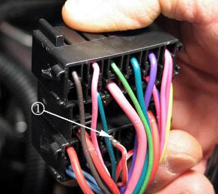
These conditions may be caused by poor electrical contact between the underhood fuse block (UBEC) and its connectors. This poor contact may be due a bent or twisted male terminal (as shown above) on the UBEC side. During assembly when the UBEC is bolted to the connectors, the male terminal contacts the edge of the mating female terminal and pushes the terminal (1) out of the cavity. When this occurs, the terminal lock on the connector breaks and the terminal will no longer lock into the connector.
Correction
Remove the UBEC from the connectors. Visually inspect the suspect connector to see if the terminal has been pushed out of its cavity. If the terminal has been pushed out of its cavity, the terminal lock is damaged and connector replacement is required. Also, inspect the terminal for damage and replace if necessary. Straighten the UBEC male terminal (use a business card as a straight edge). If the terminal is twisted, attempt to straighten it using needle nose pliers.
Parts Information
Part Number Description
88988759 Connector, Engine Wiring (C1 or X1)
88988756 Connector, Engine Wiring (C2 or X2)
19115601 Connector, Engine Wiring (C3 or X3)
19115600 Connector, Engine Wiring (C4 or X4)
Subject: Intermittent No Start/Long Crank, Start Then Stall, Check Engine Light On, Airbag Light On, Reduced Power Steering Assist, Intermittently Functioning or Inoperative Electrical Systems, DTC P0442 or P0449 Set (Inspect UBEC and Replace Connectors, As Necessary)
Models: 2006-2009 Chevrolet HHR
2006-2009 Pontiac Solstice
2007-2009 Saturn SKY
2007-2009 Opel GT
2007-2008 Daewoo G2X
Condition
Some customers may comment about one or more of the following conditions:
� Intermittent no start
� Intermittent extended crank
� Intermittent start then stall
� Intermittent check engine light illuminated
� Intermittent reduced power steering assist
� Intermittent airbag light illuminated
� Intermittently functioning or inoperative electrical systems
Upon investigation, the technician may find DTC P0442 or P0449 set as current or in history. These DTCs may also be accompanied by other DTCs.
Cause
These conditions may be caused by poor electrical contact between the underhood fuse block (UBEC) and its connectors. This poor contact may be due a bent or twisted male terminal (as shown above) on the UBEC side. During assembly when the UBEC is bolted to the connectors, the male terminal contacts the edge of the mating female terminal and pushes the terminal (1) out of the cavity. When this occurs, the terminal lock on the connector breaks and the terminal will no longer lock into the connector.
Correction
Remove the UBEC from the connectors. Visually inspect the suspect connector to see if the terminal has been pushed out of its cavity. If the terminal has been pushed out of its cavity, the terminal lock is damaged and connector replacement is required. Also, inspect the terminal for damage and replace if necessary. Straighten the UBEC male terminal (use a business card as a straight edge). If the terminal is twisted, attempt to straighten it using needle nose pliers.
Parts Information
Part Number Description
88988759 Connector, Engine Wiring (C1 or X1)
88988756 Connector, Engine Wiring (C2 or X2)
19115601 Connector, Engine Wiring (C3 or X3)
19115600 Connector, Engine Wiring (C4 or X4)
06-25-2009, 05:46 PM
#86
Founding Member
Thread Starter
Join Date: 11-23-2007
Location: Texas
Posts: 8,210
09-09-41-004
#: Instrument Panel Cluster (IPC) Air Bag Indicator Illuminated (Install Protective Material) - (Jun 23, 2009)
Subject: Instrument Panel Cluster (IPC) Air Bag Indicator Illuminated (Install Protective Material)
Models: 2007-2009 Chevrolet Cobalt
2008-2009 Chevrolet HHR SS
2006-2009 Pontiac Solstice
2007-2009 Pontiac G5
2007-2009 Saturn SKY
2007-2009 Opel GT
2007-2008 Daewoo G2X
Built Prior to 02-02-09
--------------------------------------------------------------------------------
Condition
Some customers may comment that the air bag indicator lamp, located in the instrument panel cluster, is illuminated.
Upon performing a DTC check, the technician may find a B0012-02, B0012-0E, B0013-02 or B0013-0E code stored in the supplemental inflatable restraints (SIR) system.
Cause
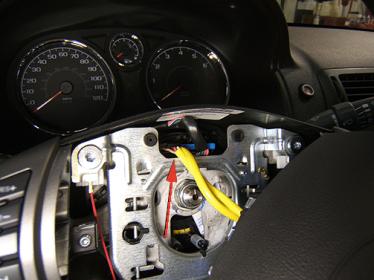
This condition may be caused by a short to ground in the yellow SIR wiring harness. This wiring harness is located within the steering wheel assembly and connects the steering wheel inflatable restraint module to the steering wheel inflatable restraint module coil. A sharp edge on the steering wheel stamped steel horn plate may rub through the yellow SIR wiring harness insulation, allowing the harness to ground to the horn plate.
Correction
Remove the steering wheel inflatable restraint module. Refer to Steering Wheel Inflatable Restraint Module Replacement in SI.
Inspect the yellow SIR wiring harness that connects the steering wheel inflatable restraint module to the steering wheel inflatable restraint module coil. Look for any chafing, cracks or areas where the wiring, insulation or protective wire sleeve has been damaged.
If the inspection of the wiring harness reveals a condition that may allow the wiring to short to ground, replace the steering wheel inflatable restraint module coil. Refer to Steering Wheel Inflatable Restraint Module Coil Replacement in SI for replacement procedures.
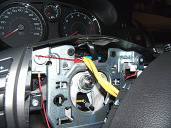
With the steering wheel inflatable restraint removed, use the following steps to install a piece of adhesive-backed flocking material to the stamped steel horn plate in order to prevent future damage to the SIR wiring harness.
4.1. Prepare a 15 mm (19/32 in) X 70 mm (2-3/4 in) piece of adhesive-backed flocking material (such as Kent Industries Part KY13487* or the equivalent).
4.2. Install the flocking material to the stamped steel horn plate as shown. Center the length of the flocking material on the horizontal edge of the opening in the horn plate. Ensure that 5-7 mm (1/4 in) of the flocking material overlaps the front and back of the horn plate. The flocking material must cover the complete length of the horizontal opening. Press (pinch) along the length of the flocking material to ensure adhesion to the horn plate.
Install the steering wheel inflatable restraint module. Refer to Steering Wheel Inflatable Restraint Module Replacement in SI.
* We believe this source and their products to be reliable. There may be additional manufacturers of such products/materials. General Motors does not endorse, indicate any preference for, or assume any responsibility for the products or material from this firm or for any such items that may be available from other sources.
Parts Information
This product is currently available from Kent Industries (1-888-YES-KENT).
Part Number Description Quantity
KT13487 BRS Adhesive-Backed Flocked Material 15 mm (19/32 in) X 70 mm (2-3/4 in)
Subject: Instrument Panel Cluster (IPC) Air Bag Indicator Illuminated (Install Protective Material)
Models: 2007-2009 Chevrolet Cobalt
2008-2009 Chevrolet HHR SS
2006-2009 Pontiac Solstice
2007-2009 Pontiac G5
2007-2009 Saturn SKY
2007-2009 Opel GT
2007-2008 Daewoo G2X
Built Prior to 02-02-09
--------------------------------------------------------------------------------
Condition
Some customers may comment that the air bag indicator lamp, located in the instrument panel cluster, is illuminated.
Upon performing a DTC check, the technician may find a B0012-02, B0012-0E, B0013-02 or B0013-0E code stored in the supplemental inflatable restraints (SIR) system.
Cause
This condition may be caused by a short to ground in the yellow SIR wiring harness. This wiring harness is located within the steering wheel assembly and connects the steering wheel inflatable restraint module to the steering wheel inflatable restraint module coil. A sharp edge on the steering wheel stamped steel horn plate may rub through the yellow SIR wiring harness insulation, allowing the harness to ground to the horn plate.
Correction
Remove the steering wheel inflatable restraint module. Refer to Steering Wheel Inflatable Restraint Module Replacement in SI.
Inspect the yellow SIR wiring harness that connects the steering wheel inflatable restraint module to the steering wheel inflatable restraint module coil. Look for any chafing, cracks or areas where the wiring, insulation or protective wire sleeve has been damaged.
If the inspection of the wiring harness reveals a condition that may allow the wiring to short to ground, replace the steering wheel inflatable restraint module coil. Refer to Steering Wheel Inflatable Restraint Module Coil Replacement in SI for replacement procedures.
With the steering wheel inflatable restraint removed, use the following steps to install a piece of adhesive-backed flocking material to the stamped steel horn plate in order to prevent future damage to the SIR wiring harness.
4.1. Prepare a 15 mm (19/32 in) X 70 mm (2-3/4 in) piece of adhesive-backed flocking material (such as Kent Industries Part KY13487* or the equivalent).
4.2. Install the flocking material to the stamped steel horn plate as shown. Center the length of the flocking material on the horizontal edge of the opening in the horn plate. Ensure that 5-7 mm (1/4 in) of the flocking material overlaps the front and back of the horn plate. The flocking material must cover the complete length of the horizontal opening. Press (pinch) along the length of the flocking material to ensure adhesion to the horn plate.
Install the steering wheel inflatable restraint module. Refer to Steering Wheel Inflatable Restraint Module Replacement in SI.
* We believe this source and their products to be reliable. There may be additional manufacturers of such products/materials. General Motors does not endorse, indicate any preference for, or assume any responsibility for the products or material from this firm or for any such items that may be available from other sources.
Parts Information
This product is currently available from Kent Industries (1-888-YES-KENT).
Part Number Description Quantity
KT13487 BRS Adhesive-Backed Flocked Material 15 mm (19/32 in) X 70 mm (2-3/4 in)
07-08-2009, 01:36 PM
#87
Founding Member
Thread Starter
Join Date: 11-23-2007
Location: Texas
Posts: 8,210
pip4669A
#PIP4669A: Intermittent DTC P2261 Setting - (Aug 10, 2009)
Subject: Intermittent DTC P2261 Setting
Models: 2008-2010 Chevrolet Cobalt SS
2008-2010 Chevrolet HHR SS
--------------------------------------------------------------------------------
This PI was superseded to update model years. Please discard PIP4669.
--------------------------------------------------------------------------------
The following diagnosis might be helpful if the vehicle exhibits the symptom(s) described in this PI.
Condition/Concern:
A technician may find DTC P2261: Turbocharger Bypass Valve Stuck Closed set with no problem found. It may be intermittent in nature or they may find the dtc will set after a hard acceleration, usually in third gear. DTC P2261 is a type B dtc and will not set on the first drive cycle the dtc sets, therefore multiple test drives should be performed to confirm repair.
Recommendation/Instructions:
SI diagnostics for this DTC states that the ECM compares the measured MAF reading to the modeled MAF and has detected a series of pulsations in the induction system that exceed a calibrated threshold. A snapshot of "Induction Data" will show the fault, however the tech may need to compare the snapshot data to another vehicle if they are unfamiliar with the readings. They should note a fluctuation and or a difference in the desired versus requested boost level. When diagnosing this dtc pay close attention to Circuit/System testing step #1. This step has you inspecting for any vacuum leaks, damage, restrictions, improper routing or connecting of the vacuum hoses on the charge air bypass valve solenoid, the charge air bypass valve, and the charge air bypass valve vacuum tank.
We have found leaking vacuum tanks causing this dtc. When testing the vacuum tank, care must be used or the results may not be valid. The vacuum tank has an integral check valve not noted in SI. To check the Vacuum Tank operation, disconnect the hose that runs from the tank to the Bypass Valve Solenoid at the solenoid and apply vacuum to the tank. The tank should be able to maintain vacuum with no decay. Note: If you remove the vacuum hose from the intake manifold and plug it and the decay stops the check valve is leaking, if the decay continues the tank itself is leaking.
Note: Front wheel drive platforms using the 2.0 Liter RPO (LNF) incorporate a charge air bypass valve supplemental vacuum tank. The purpose of the tank is to provide an instant source of vacuum to the bypass valve via the bypass solenoid (when it is commanded open by the ECM). This results in less pressure buildup under closed throttle conditions, thereby reducing compressor noise, surge and spool time.
Last edited by ChevyMgr; 08-11-2009 at 09:33 AM.
07-22-2009, 10:18 AM
#88
Founding Member
Thread Starter
Join Date: 11-23-2007
Location: Texas
Posts: 8,210
09126
#09126: Service Update for Inventory and Customer Vehicles-Charge Air Cooler Inlet Duct Detachment - (Jul 21, 2009)
Subject: 09126 -- Service Update for Inventory and Customer Vehicles - Charge Air Cooler Inlet Duct Detachment - Expires with Base Warranty
Models: 2008-2009 Chevrolet Cobalt SS, HHR SS
Equipped with a Manual Transmission
--------------------------------------------------------------------------------
THIS SERVICE UPDATE INCLUDES VEHICLES IN DEALER INVENTORY AND CUSTOMER VEHICLES THAT RETURN TO THE DEALERSHIP FOR ANY REASON. IT WILL EXPIRE AT THE END OF THE INVOLVED VEHICLE'S NEW VEHICLE LIMITED WARRANTY PERIOD.
Purpose
This bulletin provides a service procedure to install a new stud and retainer on certain 2008-2009 model year Chevrolet Cobalt SS and HHR SS vehicles equipped with a manual transmission. On these vehicles, the charge air cooler inlet duct may become detached and contact the high pressure fuel pump connector. This contact could eventually cause damage to the connector, causing the fuel pump to become inoperative. If this were to happen, the Engine Power Reduced message would illuminate in the DIC and the maximum vehicle speed would be reduced to 20 mph (32 km/h).
This service procedure should be completed as soon as possible on involved vehicles currently in dealer inventory and customer vehicles that return to the dealer for any type of service during the New Vehicle Limited Warranty coverage period.
Vehicles Involved
A list of involved vehicles currently in dealer inventory is available on the "Service Update Bulletin Information" link under the "Service" tab in GM GlobalConnect (US) or attached to the Dealer Communication (Canada) used to release this bulletin. Customer vehicles that return for service, for any reason, and are still covered under the vehicle's base warranty, and are within the VIN breakpoints provided below, should be checked for vehicle eligibility in the appropriate system listed below.
Year Division Model From Through
2008 Chevrolet Cobalt SS 87229258 8735153
2009 Chevrolet Cobalt SS 97100001 97254608
2008 Chevrolet HHR SS 8S581592 8S722574
2009 Chevrolet HHR SS 9S500006 9S621588
Important: Dealers are to confirm vehicle eligibility prior to beginning repairs by using the GM Vehicle Inquiry System (GMVIS). Not all vehicles within the above breakpoints may be involved.
Parts Information
Parts required to complete this service update are to be obtained from General Motors Service and Parts Operations (GMSPO). Please refer to your "involved vehicles listing" before ordering parts. Normal orders should be placed on a DRO = Daily Replenishment Order. In an emergency situation, parts should be ordered on a CSO = Customer Special Order.
Part Number Description Qty/ Vehicle
11570937 Stud, Chrg Air Clr Brkt Plt 1
90278102 Retainer, Chrg Air Clr 1
Service Procedure
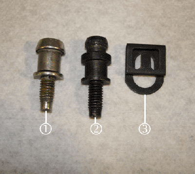
(1) First Design Stud
(2) Second Design Stud
(3) Retainer Clip
Open the hood.
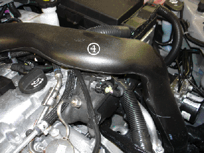
Locate the charge air cooler (CAC) duct (4).
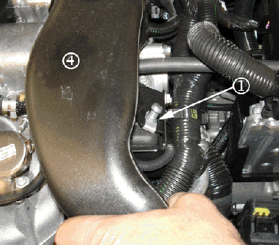
Remove the CAC duct (4) off of the first design mounting stud (1).
Remove and discard the first design mounting stud (1).
Install the second design mounting stud (2).

Secure the CAC duct (4) onto the second design mounting stud.
Install the retainer clip (3) to the second design mounting stud. Ensure that the retainer clip is installed properly.
Close the hood.
Subject: 09126 -- Service Update for Inventory and Customer Vehicles - Charge Air Cooler Inlet Duct Detachment - Expires with Base Warranty
Models: 2008-2009 Chevrolet Cobalt SS, HHR SS
Equipped with a Manual Transmission
--------------------------------------------------------------------------------
THIS SERVICE UPDATE INCLUDES VEHICLES IN DEALER INVENTORY AND CUSTOMER VEHICLES THAT RETURN TO THE DEALERSHIP FOR ANY REASON. IT WILL EXPIRE AT THE END OF THE INVOLVED VEHICLE'S NEW VEHICLE LIMITED WARRANTY PERIOD.
Purpose
This bulletin provides a service procedure to install a new stud and retainer on certain 2008-2009 model year Chevrolet Cobalt SS and HHR SS vehicles equipped with a manual transmission. On these vehicles, the charge air cooler inlet duct may become detached and contact the high pressure fuel pump connector. This contact could eventually cause damage to the connector, causing the fuel pump to become inoperative. If this were to happen, the Engine Power Reduced message would illuminate in the DIC and the maximum vehicle speed would be reduced to 20 mph (32 km/h).
This service procedure should be completed as soon as possible on involved vehicles currently in dealer inventory and customer vehicles that return to the dealer for any type of service during the New Vehicle Limited Warranty coverage period.
Vehicles Involved
A list of involved vehicles currently in dealer inventory is available on the "Service Update Bulletin Information" link under the "Service" tab in GM GlobalConnect (US) or attached to the Dealer Communication (Canada) used to release this bulletin. Customer vehicles that return for service, for any reason, and are still covered under the vehicle's base warranty, and are within the VIN breakpoints provided below, should be checked for vehicle eligibility in the appropriate system listed below.
Year Division Model From Through
2008 Chevrolet Cobalt SS 87229258 8735153
2009 Chevrolet Cobalt SS 97100001 97254608
2008 Chevrolet HHR SS 8S581592 8S722574
2009 Chevrolet HHR SS 9S500006 9S621588
Important: Dealers are to confirm vehicle eligibility prior to beginning repairs by using the GM Vehicle Inquiry System (GMVIS). Not all vehicles within the above breakpoints may be involved.
Parts Information
Parts required to complete this service update are to be obtained from General Motors Service and Parts Operations (GMSPO). Please refer to your "involved vehicles listing" before ordering parts. Normal orders should be placed on a DRO = Daily Replenishment Order. In an emergency situation, parts should be ordered on a CSO = Customer Special Order.
Part Number Description Qty/ Vehicle
11570937 Stud, Chrg Air Clr Brkt Plt 1
90278102 Retainer, Chrg Air Clr 1
Service Procedure
(1) First Design Stud
(2) Second Design Stud
(3) Retainer Clip
Open the hood.
Locate the charge air cooler (CAC) duct (4).
Remove the CAC duct (4) off of the first design mounting stud (1).
Remove and discard the first design mounting stud (1).
Install the second design mounting stud (2).
Secure the CAC duct (4) onto the second design mounting stud.
Install the retainer clip (3) to the second design mounting stud. Ensure that the retainer clip is installed properly.
Close the hood.
07-22-2009, 10:45 AM
#89
Founding Member
Thread Starter
Join Date: 11-23-2007
Location: Texas
Posts: 8,210
09-06-93-004
#09-06-93-004: Intermittent MIL/Check Engine Light On, DTC P0299 or P0234 Set (Adjust Turbocharger Wastegate Actuator) - (Jul 21, 2009)
Subject: Intermittent MIL/Check Engine Light On, DTC P0299 or P0234 Set (Adjust Turbocharger Wastegate Actuator)
Models: 2008-2009 Chevrolet Cobalt, HHR
2008-2009 Pontiac Solstice GXP
2008-2009 Saturn SKY Redline
2008-2009 Opel GT
2008 Daewoo G2X
with Engine RPO LNF and LDK (Europe)
Please Refer to GMVIS
--------------------------------------------------------------------------------
Condition
Some customers may comment that the SES light is on. Upon inspection, you may find DTC P0299 (Turbocharger Engine Underboost) or P0234 (Turbocharger Engine Overboost) set.
Cause
This condition may be caused by a mis-adjusted wastegate.
Correction
Note: The wastegate adjustment is sometimes a very fine process. When adjusting the wastegate, only small adjustments should be made. Loosen one nut at a time and only adjust the nut one turn at a time; then tighten the other nut against the shaft and test drive to verify. This may have to be performed several times to achieve the desired boost level. To ensure proper adjustment, the vehicle should be at full operating temperature when testing. The vehicle will be very hot and may need to cool between adjustments. Too large of an adjustment can cause repeat DTCs.
Adjust the turbocharger wastegate. Refer to Turbocharger Wastegate Actuator Adjustment in SI.
Troubleshooting Tips for DTC P0299 - Turbocharger Engine Underboost
To increase boost, adjust the nuts (in) towards the actuator; in essence making the shaft shorter.
Troubleshooting Tips for DTC P0234 - Turbocharger Engine Overboost
To reduce boost, adjust the nuts (out) towards the end of the shaft; in essence making the shaft longer.
07-22-2009, 10:54 AM
#90
Founding Member
Thread Starter
Join Date: 11-23-2007
Location: Texas
Posts: 8,210
09-07-29-004
#09-07-29-004: Information on Revised Getrag 5-Speed Manual Transmission (RPO M86) Fluid Usage - (Jul 14, 2009)
Subject: Information on Revised Getrag 5-Speed Manual Transmission (RPO M86) Fluid Usage
Models: 2008 Chevrolet HHR
Equipped with Manual Transmission (RPO M86)
--------------------------------------------------------------------------------
For 2008, the transmission fluid for the manual transmission (2.2L and 2.4L L4 engines) in the Owner Manual lists manual transmission fluid P/N 88861801. This fluid part number is incorrect.
Use DEXRON-VI� P/N 88861003 (U.S.) (in Canada, P/N 88861004) when replacing manual transmission fluid. DEXRON-VI� usage begins in 2008-2010. Please make this correction to the Owner Manual to reflect the correct part number.
Parts Information Part Number Description
88861003 (US)
88861004 (Canada) DEXRON-VI�