Official TSB and Recall Thread
 05-20-2009, 02:12 PM
#71
Founding Member
Thread Starter

Join Date: 11-23-2007
Location: Texas
Posts: 8,210
09-08-44-013b
#09-08-44-013B: Information on USB Command and Control Multimedia Player Interface/List of Supported Devices - (Mar 11, 2010)
Subject: Information on USB Command and Control Multimedia Player Interface/List of Supported Devices
Models: 2010 Buick Enclave, LaCrosse
2008-2010 Cadillac CTS
2010 Cadillac Escalades, SRX
2009-2010 Chevrolet Cobalt, HHR, Malibu
2010 Chevrolet Avalanche, Camaro, Equinox, Silverado, Suburban, Tahoe, Traverse
2010 GMC Acadia, Sierra, Terrain, Yukons
2009-2010 Pontiac G5, G6, Solstice, Solstice Coupe
2009-2010 Saturn AURA, SKY
2010 Saturn OUTLOOK
All Equipped with Convenience and Connectivity Package - RPOs KTA, KTB, SRJ, U4H, UUI, UUJ, UUM, UUN, U2S, U2X, U2Y, UAV, UYZ, UY5
--------------------------------------------------------------------------------
This bulletin is being revised to add the RPO U4H. Please discard Corporate Bulletin Number 09-08-44-013A (Section 08 - Body and Accessories).
--------------------------------------------------------------------------------
USB Radio and MP3 Functionality
The USB (Universal Serial Bus) will be a USB 2.0 port on the radio faceplate, on the IP or in the center console. This interface will give the customer the additional functionality of iPod/MP3 command and control. Customers now have full radio control of the iPod/MP3 audio files via the USB cable. A single USB connection allows digital audio transferring from the iPod to the radio. The customer will also have playback capability with a USB memory stick (only MP3 and WMA files).
Note: Not all memory sticks are supported.
Customers have full radio control of the iPod/MP3 audio files via the USB cable. A single USB connection allows digital audio transferring from the iPod to the radio. The iPod will be charging while connected to the radio.
Note: Video from the iPod is NOT capable of being transferred to a Navigation radio display.
For the Chevrolet Cobalt, HHR and Malibu; Pontiac G5, G6, Solstice; and Saturn AURA, SKY, the USB port is on the faceplate of the radio. For all other models, it is located in the center console or IP.
For the Cadillac CTS only, a special iPod cable (USB and AUX cable) is needed. This special cable comes delivered with the vehicle. In all cases, the iPod will be charging while connected to the radio through the USB port when the vehicle is running or the RPA is active.
Problems with iPod Not Connecting
If the infotainment system does not operate properly when using a device connected through the USB port, this may be due to an incompatible media device.
Important: DO NOT replace the radio or multimedia interface module due to a customer device incompatibility issue.
Verify the customer's media device is validated for this system using the list below. If the customer's device is a validated device for this system, follow the SI diagnostic procedure to isolate the fault. If the customer's device is not on the validated device list, explain to the customer that their particular unit is not compatible with the system.
Troubleshooting Tips for iPod Devices
Check the version of the iPod/MP3 to confirm that it is supported.
Unplug and Re-insert the iPod to verify the customer complaint.
Verify the battery charge of the iPod. A low battery condition on the iPod may not allow it to connect to the radio. The iPod may need to be charged before it can be controlled by the radio.
If the customer receives a "Device Not Supported" message on their radio or is having general iPod/MP3 connection issues (and they have a supported device), they may need to reset their iPod. To reset the iPod:
• For the iPod Nanos and Classic , Toggle the Hold switch on and off. (Slide it to Hold, then turn it off again. Press and hold the Menu and Center (Select) buttons simultaneously until the Apple logo appears, about 6 to 8 seconds. You may need to repeat this step.
• For the iPod Touch and iPhone: Press and hold the Sleep/Wake button for a few seconds until the red slider appears, then slide the slider.
Have the customer check their cable for quality.
• Aftermarket cables can wear from use. The customer may need to purchase a new USB cable.
• Verify that cable extensions are not present. The extra capacitance may cause too large a signal drop for the iPod to communicate with the radio.
If the customer receives a "Device Not Supported" message on their radio with an iPod connected (and they have a supported device), the customer may need to download the latest firmware from the Apple website (Please visit www.apple.com for more information).
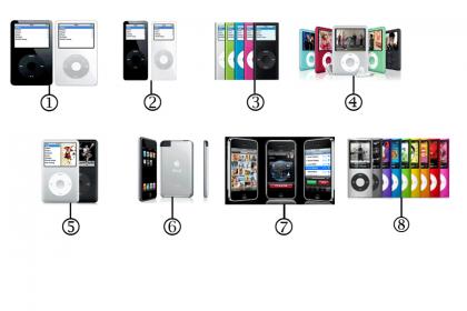
Validated Apple Device - Both Charge/Support Digital Audio (For All RPOs)
For further information on identifying iPod models, please visit http://support.apple.com/kb/HT1353
Brand Name/Description Number
Apple iPod Classic 5 & 5.5 Gen 1
Apple iPod Nano 1Gen 2
Apple iPod Nano 2Gen 3
Apple iPod Nano 3 4
Apple iPod Classic 5
Apple iPod Touch 1Gen & 2Gen 6
Apple iPhone (User must switch to "airplane mode") 7
Apple iPod Nano 4 GEN 8
Other Validated Device-- Both Charge/Support Digital Audio for Buick LaCrosse, Chevrolet Camaro, Equinox Only (RPO KTA or KTB)
Important: : Must be set to MTP (Mass Transfer Protocol) in the MP3 Player device setting.
Brand Name/Description
SanDisk Sansa e280
Toshiba Gigabeat
Philips Philips GoGear
Sony Sony NWZ-A828
Sony Sony NWZ-S616F
Insignia Insignia
Iriver Iriver Clix
Iriver H10
Samsung S5J AB/XAA(4GB)
Samsung T10
Samsung Yepp S5
Microsoft Zune (Gen 1 & 2)
Important: These devices (and additional MP3 players) may be capable of connecting to the other USB options by internally setting the MP3 device to MSC (Mass Storage Class) mode. In this mode, the USB port will see the device as a flash drive. Please have the customer refer to their MP3 device manual on how to set the device to MSC. If the device is not able to be set to MSC, the customer must use the AUX jack.
Note: MTP mode must be used in order to transfer ANY Digital Rights Managment (DRM) protected content.
Non-Validated Apple Device
Important: The following devices are NOT supported by USB interface. Apple does not support digital media transfer from these devices through the USB port. The customer can still listen to their older iPod on vehicle by connecting it to the Auxiliary Input Jack using a standard 3.5mm (1/8 in) stereo cable.
Brand Description Number
Apple iPod Shuffle Gen1 1
Apple iPod Shuffle Gen2 2
Apple iPod mini Gen1&2 3
Apple iPod Photo 4
Apple iPod G4 5
Apple iPod Gen3 6
Apple iPod Gen2 7
Apple iPod Gen1 8
Apple iPod Shuffle Gen 3 9
Subject: Information on USB Command and Control Multimedia Player Interface/List of Supported Devices
Models: 2010 Buick Enclave, LaCrosse
2008-2010 Cadillac CTS
2010 Cadillac Escalades, SRX
2009-2010 Chevrolet Cobalt, HHR, Malibu
2010 Chevrolet Avalanche, Camaro, Equinox, Silverado, Suburban, Tahoe, Traverse
2010 GMC Acadia, Sierra, Terrain, Yukons
2009-2010 Pontiac G5, G6, Solstice, Solstice Coupe
2009-2010 Saturn AURA, SKY
2010 Saturn OUTLOOK
All Equipped with Convenience and Connectivity Package - RPOs KTA, KTB, SRJ, U4H, UUI, UUJ, UUM, UUN, U2S, U2X, U2Y, UAV, UYZ, UY5
--------------------------------------------------------------------------------
This bulletin is being revised to add the RPO U4H. Please discard Corporate Bulletin Number 09-08-44-013A (Section 08 - Body and Accessories).
--------------------------------------------------------------------------------
USB Radio and MP3 Functionality
The USB (Universal Serial Bus) will be a USB 2.0 port on the radio faceplate, on the IP or in the center console. This interface will give the customer the additional functionality of iPod/MP3 command and control. Customers now have full radio control of the iPod/MP3 audio files via the USB cable. A single USB connection allows digital audio transferring from the iPod to the radio. The customer will also have playback capability with a USB memory stick (only MP3 and WMA files).
Note: Not all memory sticks are supported.
Customers have full radio control of the iPod/MP3 audio files via the USB cable. A single USB connection allows digital audio transferring from the iPod to the radio. The iPod will be charging while connected to the radio.
Note: Video from the iPod is NOT capable of being transferred to a Navigation radio display.
For the Chevrolet Cobalt, HHR and Malibu; Pontiac G5, G6, Solstice; and Saturn AURA, SKY, the USB port is on the faceplate of the radio. For all other models, it is located in the center console or IP.
For the Cadillac CTS only, a special iPod cable (USB and AUX cable) is needed. This special cable comes delivered with the vehicle. In all cases, the iPod will be charging while connected to the radio through the USB port when the vehicle is running or the RPA is active.
Problems with iPod Not Connecting
If the infotainment system does not operate properly when using a device connected through the USB port, this may be due to an incompatible media device.
Important: DO NOT replace the radio or multimedia interface module due to a customer device incompatibility issue.
Verify the customer's media device is validated for this system using the list below. If the customer's device is a validated device for this system, follow the SI diagnostic procedure to isolate the fault. If the customer's device is not on the validated device list, explain to the customer that their particular unit is not compatible with the system.
Troubleshooting Tips for iPod Devices
Check the version of the iPod/MP3 to confirm that it is supported.
Unplug and Re-insert the iPod to verify the customer complaint.
Verify the battery charge of the iPod. A low battery condition on the iPod may not allow it to connect to the radio. The iPod may need to be charged before it can be controlled by the radio.
If the customer receives a "Device Not Supported" message on their radio or is having general iPod/MP3 connection issues (and they have a supported device), they may need to reset their iPod. To reset the iPod:
• For the iPod Nanos and Classic , Toggle the Hold switch on and off. (Slide it to Hold, then turn it off again. Press and hold the Menu and Center (Select) buttons simultaneously until the Apple logo appears, about 6 to 8 seconds. You may need to repeat this step.
• For the iPod Touch and iPhone: Press and hold the Sleep/Wake button for a few seconds until the red slider appears, then slide the slider.
Have the customer check their cable for quality.
• Aftermarket cables can wear from use. The customer may need to purchase a new USB cable.
• Verify that cable extensions are not present. The extra capacitance may cause too large a signal drop for the iPod to communicate with the radio.
If the customer receives a "Device Not Supported" message on their radio with an iPod connected (and they have a supported device), the customer may need to download the latest firmware from the Apple website (Please visit www.apple.com for more information).
Validated Apple Device - Both Charge/Support Digital Audio (For All RPOs)
For further information on identifying iPod models, please visit http://support.apple.com/kb/HT1353
Brand Name/Description Number
Apple iPod Classic 5 & 5.5 Gen 1
Apple iPod Nano 1Gen 2
Apple iPod Nano 2Gen 3
Apple iPod Nano 3 4
Apple iPod Classic 5
Apple iPod Touch 1Gen & 2Gen 6
Apple iPhone (User must switch to "airplane mode") 7
Apple iPod Nano 4 GEN 8
Other Validated Device-- Both Charge/Support Digital Audio for Buick LaCrosse, Chevrolet Camaro, Equinox Only (RPO KTA or KTB)
Important: : Must be set to MTP (Mass Transfer Protocol) in the MP3 Player device setting.
Brand Name/Description
SanDisk Sansa e280
Toshiba Gigabeat
Philips Philips GoGear
Sony Sony NWZ-A828
Sony Sony NWZ-S616F
Insignia Insignia
Iriver Iriver Clix
Iriver H10
Samsung S5J AB/XAA(4GB)
Samsung T10
Samsung Yepp S5
Microsoft Zune (Gen 1 & 2)
Important: These devices (and additional MP3 players) may be capable of connecting to the other USB options by internally setting the MP3 device to MSC (Mass Storage Class) mode. In this mode, the USB port will see the device as a flash drive. Please have the customer refer to their MP3 device manual on how to set the device to MSC. If the device is not able to be set to MSC, the customer must use the AUX jack.
Note: MTP mode must be used in order to transfer ANY Digital Rights Managment (DRM) protected content.
Non-Validated Apple Device
Important: The following devices are NOT supported by USB interface. Apple does not support digital media transfer from these devices through the USB port. The customer can still listen to their older iPod on vehicle by connecting it to the Auxiliary Input Jack using a standard 3.5mm (1/8 in) stereo cable.
Brand Description Number
Apple iPod Shuffle Gen1 1
Apple iPod Shuffle Gen2 2
Apple iPod mini Gen1&2 3
Apple iPod Photo 4
Apple iPod G4 5
Apple iPod Gen3 6
Apple iPod Gen2 7
Apple iPod Gen1 8
Apple iPod Shuffle Gen 3 9
Last edited by ChevyMgr; 03-12-2010 at 12:24 PM.
 05-28-2009, 03:27 PM
#72
Founding Member
Thread Starter
Join Date: 11-23-2007
Location: Texas
Posts: 8,210
08-06-04-033c
#08-06-04-033C: Identifying Aftermarket Engine and Transmission Calibrations 2.0L, 2.2L, 2.4L, 2.8L, 2.9L, 3.0L, 3.1L, 3.2L, 3.4L 3.5L, 3.6L, 3.8L, 3.9L, 4.2L, 4.3L, 4.4L, 4.6L, 5.0L, 5.3L, 5.7L 6.0L, 6.2L 7.0L, 7.4L - (Dec 18, 2008)
Subject: Identifying Aftermarket Engine and Transmission Calibrations 2.0L, 2.2L, 2.4L, 2.8L, 2.9L, 3.0L, 3.1L, 3.2L, 3.4L, 3.5L, 3.6L, 3.8L, 3.9L, 4.2L, 4.3L, 4.4L, 4.6L, 4.8L, 5.0L, 5.3L, 5.7L, 6.0L, 6.2L, 7.0L, 7.4L, 8.1L Gas Powered Engines Only and 6T40/45 (MH8), 6T70/75 (MH2, MH4, MH6, MY9), 6L50 (MYB) 6L80 (MYC) or 6L90 (MYD) Automatic Transmission
Models: 2006-2009 GM Passenger Cars and Light Duty Trucks
2006-2009 HUMMER H2, H3
2006-2009 Saturn Models
2006-2009 Opel GT
2007-2008 Daewoo G2X
EXCLUDING Chevrolet Aveo, Pontiac Vibe, Wave, G3, Saab Models, Saturn ASTRA
--------------------------------------------------------------------------------
This bulletin is being revised to remove Saturn (except Astra) from the list of excluded vehicles. Please discard Corporate Bulletin Number 08-06-04-033B (Section 06 -- Engine/Propulsion System).
--------------------------------------------------------------------------------
Important: This bulletin applies to Gas Powered Engines ONLY. For Diesel Powered Engines, refer to Service Bulletin #08-06-04-006C.
If a suspicious hard part failure is observed in the engine, transmission, transfer case or driveline, perform the calibration verification described to determine if a non-GM issued engine calibration is installed. Non-GM issued engine calibrations subject driveline components to stresses different from the calibrations that these components were validated to. Repairs to engine, transmission, transfer case and/or other driveline components where a non-GM engine calibration has been verified are not covered under the terms of the New Vehicle Warranty.
Instructions for Confirming Calibration Verification Number (CVN):
Go to TIS2WEB
Select "Calibration Information (SPS Info)"
Enter VIN
Select "Get Cal ID"
Select "ECM Engine Control Module" or "TCM Transmission Control Module"
Select "Next"
Select "Complete History"
Print
Take the printout to the vehicle along with the Tech 2�
Plug in the Tech 2�
Go to diagnostics and build the vehicle
Select "Powertrain"
Select "Engine"
*Select "Engine Control Module" or "PCM" or "TCM"
*Select "Module ID Information" or "I/M Information System" if module ID information selection is not available.
*If "I/M information System" was selected in step 15, it may be necessary to select "Vehicle Information" in order to display the calibration information.
Compare the calibration ID and Calibration Verification Numbers (CVN) to the Calibration Verification Numbers (CVN) on the printout.
* Steps may vary by controller.
Although the part numbers will be the same for each, it's the CVN that will determine if the calibration is GM issued. If ALL of the CVN's are EXACTLY the same, the calibration is GM issued.
If the part numbers match and ANY CVN's DO NOT match the printout, it is likely that a non-GM certified calibration has been installed.
If the CVN information is displayed as "N/A", it will be necessary to contact the TCSC to obtain the CVN information.
If a non-GM calibration is found to be in the ECM or TCM (CVN's on the Tech 2� do not match TIS printout) - In order to document the case -- a CLEAR digital picture should be taken of the Tech 2� screen showing the VIN and the CVNs that do not match the TIS2WEB printout. The picture, VIN and reason the vehicle is currently in for service should be emailed to xxxxxx for verification. Please copy your GM District Service Manager (DVM) on the e-mail. In Canada, please copy your GM Warranty Manager. GM will verify if the CVNs are not GM issued and respond via e-mail within 72 hours.
Subject: Identifying Aftermarket Engine and Transmission Calibrations 2.0L, 2.2L, 2.4L, 2.8L, 2.9L, 3.0L, 3.1L, 3.2L, 3.4L, 3.5L, 3.6L, 3.8L, 3.9L, 4.2L, 4.3L, 4.4L, 4.6L, 4.8L, 5.0L, 5.3L, 5.7L, 6.0L, 6.2L, 7.0L, 7.4L, 8.1L Gas Powered Engines Only and 6T40/45 (MH8), 6T70/75 (MH2, MH4, MH6, MY9), 6L50 (MYB) 6L80 (MYC) or 6L90 (MYD) Automatic Transmission
Models: 2006-2009 GM Passenger Cars and Light Duty Trucks
2006-2009 HUMMER H2, H3
2006-2009 Saturn Models
2006-2009 Opel GT
2007-2008 Daewoo G2X
EXCLUDING Chevrolet Aveo, Pontiac Vibe, Wave, G3, Saab Models, Saturn ASTRA
--------------------------------------------------------------------------------
This bulletin is being revised to remove Saturn (except Astra) from the list of excluded vehicles. Please discard Corporate Bulletin Number 08-06-04-033B (Section 06 -- Engine/Propulsion System).
--------------------------------------------------------------------------------
Important: This bulletin applies to Gas Powered Engines ONLY. For Diesel Powered Engines, refer to Service Bulletin #08-06-04-006C.
If a suspicious hard part failure is observed in the engine, transmission, transfer case or driveline, perform the calibration verification described to determine if a non-GM issued engine calibration is installed. Non-GM issued engine calibrations subject driveline components to stresses different from the calibrations that these components were validated to. Repairs to engine, transmission, transfer case and/or other driveline components where a non-GM engine calibration has been verified are not covered under the terms of the New Vehicle Warranty.
Instructions for Confirming Calibration Verification Number (CVN):
Go to TIS2WEB
Select "Calibration Information (SPS Info)"
Enter VIN
Select "Get Cal ID"
Select "ECM Engine Control Module" or "TCM Transmission Control Module"
Select "Next"
Select "Complete History"
Take the printout to the vehicle along with the Tech 2�
Plug in the Tech 2�
Go to diagnostics and build the vehicle
Select "Powertrain"
Select "Engine"
*Select "Engine Control Module" or "PCM" or "TCM"
*Select "Module ID Information" or "I/M Information System" if module ID information selection is not available.
*If "I/M information System" was selected in step 15, it may be necessary to select "Vehicle Information" in order to display the calibration information.
Compare the calibration ID and Calibration Verification Numbers (CVN) to the Calibration Verification Numbers (CVN) on the printout.
* Steps may vary by controller.
Although the part numbers will be the same for each, it's the CVN that will determine if the calibration is GM issued. If ALL of the CVN's are EXACTLY the same, the calibration is GM issued.
If the part numbers match and ANY CVN's DO NOT match the printout, it is likely that a non-GM certified calibration has been installed.
If the CVN information is displayed as "N/A", it will be necessary to contact the TCSC to obtain the CVN information.
If a non-GM calibration is found to be in the ECM or TCM (CVN's on the Tech 2� do not match TIS printout) - In order to document the case -- a CLEAR digital picture should be taken of the Tech 2� screen showing the VIN and the CVNs that do not match the TIS2WEB printout. The picture, VIN and reason the vehicle is currently in for service should be emailed to xxxxxx for verification. Please copy your GM District Service Manager (DVM) on the e-mail. In Canada, please copy your GM Warranty Manager. GM will verify if the CVNs are not GM issued and respond via e-mail within 72 hours.
Last edited by ChevyMgr; 06-03-2009 at 09:51 AM.
05-29-2009, 03:38 PM
#73
Founding Member
Thread Starter
Join Date: 11-23-2007
Location: Texas
Posts: 8,210
09-06-93-002
#09-06-93-002: Turbocharger Housing Inlet Flange Cracks in Partition Wall - (May 27, 2009)
Subject: Turbocharger Housing Inlet Flange Cracks in Partition Wall
Models: 2008-2009 Chevrolet Cobalt SS, HHR SS
2007-2009 Pontiac Solstice GXP
2007-2009 Saturn SKY Redline
2007-2009 Opel GT
2007-2009 Daewoo G2X
All Equipped with Engine RPO LNF
Please Refer to GMVIS
--------------------------------------------------------------------------------
Important: DO NOT replace the turbocharger assembly for this concern.
The purpose of this bulletin is to address concerns with turbocharger housing cracks in the inlet flange partition wall. Vehicles diagnosed with various driveability concerns or turbocharger DTCs P0299 or P0234 after inspection, are revealing cracks in the inlet flange partition wall of the turbocharger housing. Turbocharger assemblies are being replaced based on the discovery of these cracks.
The pictures below illustrate typical cracks found in the turbocharger housing.
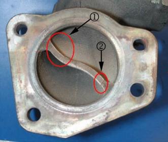
This illustration shows the location of the cracks in the partition wall of the turbocharger inlet flange on the left (1) and on the right (2).
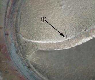
This illustration shows a close-up of the crack on the left side of the partition wall (1).
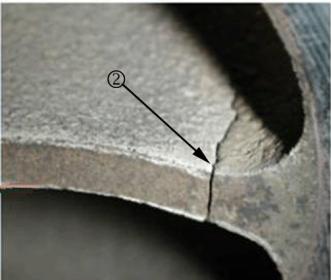
This illustration shows a close-up of the crack on the right side of the partition wall (2).
These cracks are not uncommon and are considered a normal condition and should NOT be a reason for replacing the turbocharger assembly. The cracks will not affect performance. If the vehicle exhibits driveability concerns or turbocharger DTCs P0299 or P0234 are set, refer to SI and follow the established diagnostics for correction of the customer concern.
Subject: Turbocharger Housing Inlet Flange Cracks in Partition Wall
Models: 2008-2009 Chevrolet Cobalt SS, HHR SS
2007-2009 Pontiac Solstice GXP
2007-2009 Saturn SKY Redline
2007-2009 Opel GT
2007-2009 Daewoo G2X
All Equipped with Engine RPO LNF
Please Refer to GMVIS
--------------------------------------------------------------------------------
Important: DO NOT replace the turbocharger assembly for this concern.
The purpose of this bulletin is to address concerns with turbocharger housing cracks in the inlet flange partition wall. Vehicles diagnosed with various driveability concerns or turbocharger DTCs P0299 or P0234 after inspection, are revealing cracks in the inlet flange partition wall of the turbocharger housing. Turbocharger assemblies are being replaced based on the discovery of these cracks.
The pictures below illustrate typical cracks found in the turbocharger housing.
This illustration shows the location of the cracks in the partition wall of the turbocharger inlet flange on the left (1) and on the right (2).
This illustration shows a close-up of the crack on the left side of the partition wall (1).
This illustration shows a close-up of the crack on the right side of the partition wall (2).
These cracks are not uncommon and are considered a normal condition and should NOT be a reason for replacing the turbocharger assembly. The cracks will not affect performance. If the vehicle exhibits driveability concerns or turbocharger DTCs P0299 or P0234 are set, refer to SI and follow the established diagnostics for correction of the customer concern.
05-29-2009, 03:51 PM
#74
Founding Member
Thread Starter
Join Date: 11-23-2007
Location: Texas
Posts: 8,210
07-02-32-007b
#07-02-32-007B: Diagnostic Tips for Power Steering Inoperative/Steering Wheel Hard to Turn, Power Steering Message Displayed on DIC, DTCs C0176, C0475, C0476, C0550, U2105, U2107 Set - (Aug 6, 2009)
Subject: Diagnostic Tips for Power Steering Inoperative/Steering Wheel Hard to Turn, Power Steering Message Displayed on DIC, DTCs C0176, C0475, C0476, C0550, U2105, U2107 Set
Models: 2005-2010 Chevrolet Cobalt
2006-2010 Chevrolet HHR
2005-2006 Pontiac Pursuit (Canada Only)
2007-2009 Pontiac G5
2003-2007 Saturn ION
--------------------------------------------------------------------------------
This bulletin is being revised to update the information for DTC C0475. Please discard Corporate Bulletin Number 07-02-32-007A (Section 02 -- Steering).
--------------------------------------------------------------------------------
The following diagnostics might be helpful if the vehicle exhibits the condition(s) described above. Use the appropriate recommendation based on what symptom has occurred.
No DTCs
Review Corporate Bulletin Number 05-02-32-002D to assure you do not have a blown 60 amp steering fuse. The fuse can be blown during improper jump starting of the vehicle on the HHR and ION. Check for this particularly for tow in conditions. DO NOT replace the steering column unless an internal short has been identified in the column that is causing fuse to blow.
Power Steering Warning Message on DIC with DTCs C0176 and C0476
This condition is often the result of excessive lock-to-lock turns of the steering wheel, causing the thermal protection in the power steering control module (PSCM) to take the steering motor temporarily off line. This is a normal operating characteristic of the system. DO NOT replace the steering column for this condition. Refer to Corporate Bulletin Number 06-02-32-002C for additional information.
Power Steering Warning Message on DIC with DTC C0550 in the PSCM
Inspect the motor harness connection to the PSCM. If no connector problems are found, replace the steering column ONLY as this is an internal controller issue.
Power Steering Warning Message on DIC with DTC C0475 in the PSCM
Check the connection between the EPS motor and the power steering control module (PSCM) by ensuring the harness connector is properly seated. If the connection is normal, replace ONLY the EPS motor.
Note: If the DTC resets immediately following motor replacement, replace the steering column.
Power Steering Warning Message on DIC with DTC U2105 and/or U2107 in the PSCM with any other U codes
Although the code(s) appear in the PSCM, these are communication codes and are not the result of a problem with the column operation or the control module. If the codes are in history, clear the codes and re-key the vehicle a few times to see if they come back. If they reappear, look for a communication issue from the BCM U2107 or ECM U2105 (wiring, connector, etc.) as the root cause. If the codes do not reappear after a test drive, return the vehicle back to the customer. DO NOT replace the steering column.
Last edited by ChevyMgr; 08-07-2009 at 12:47 PM.
06-01-2009, 09:31 AM
#75
Founding Member
Thread Starter
Join Date: 11-23-2007
Location: Texas
Posts: 8,210
05-02-32-002d
#05-02-32-002D: Power Steering Inoperative/Steering Wheel Hard to Turn, PWR STR Message Displayed on DIC After Jump Starting Vehicle (Replace Fuse and Instruct Owner How to Jump Start Vehicle) - (May 29, 2009)
Subject: Power Steering Inoperative/Steering Wheel Hard to Turn, "PWR STR" Message Displayed on Driver Information Center (DIC) After Jump Starting Vehicle (Replace Fuse and Instruct Owner How to Jump Start Vehicle)
Models: 2006-2009 Chevrolet HHR
2003-2007 Saturn ION
--------------------------------------------------------------------------------
This bulletin is being revised to update the model years. Please discard Corporate Bulletin Number 05-02-32-002C (Section 02 -- Steering.)
--------------------------------------------------------------------------------
Condition
Some customers may comment that the steering wheel is hard to turn and that a message of "PWR STR" is displayed on the Driver Information Center (DIC) of the instrument panel (I/P) cluster. They may also comment that this condition occurred after they had to have the vehicle jump started.
Cause
Improper "jump starting" of the vehicle has been determined as a cause for the power steering fuses to open (blow). Customers may mistakenly believe that the Underhood Junction Block (UHJB) is actually the battery; therefore, they believe there is both a positive and negative post in the UHJB. After only seeing one post, they may remove the cover and discover there is another small post on the passenger side of the UHJB. The small post on the passenger side of the UHJB is the B+ post for the electric power steering . When the jumper cables are attached to both of these posts and the cable is connected to another vehicle, the power steering fuses will blow.
Correction
Replace the blown fuses and verify that concern is eliminated.
Important: If the fuse continues to blow, refer to the appropriate diagnostic procedure below:
� For 2003-04 Saturn IONs, refer to Diagnostic System Check - Power Steering in SI or the 2003 or 2004 Saturn ION Service Manual.
� For 2005-07 Saturn IONs, refer to Diagnostic Starting Point - Power Steering System in SI or the 2005, 2006 or 2007 Saturn ION Service Manual.
� For 2006-09 Chevrolet HHRs, refer to Diagnostic Starting Point - Power Steering System in SI.
On 2003-2005 Saturn ION vehicles only, open the fuse box cover, then remove and discard the small plastic cover that has the words "REMOVE AND DISCARD THIS COVER FOR FUSE OR RELAY SERVICING" listed on the top. This cover is used only to protect the fuses upon initial factory installation.
Provide the owner with a copy of the following procedure and refer owners to Step 9 for the correct negative cable attachment point.
Jump Starting Procedure
If your vehicle's battery has run down, you may want to use another vehicle and some jumper cables to start your vehicle. Be sure to use the following steps to do it safely.
Caution: Batteries can hurt you. They can be dangerous because:
� They contain acid that can burn you.
� They contain gas that can explode or ignite.
� They contain enough electricity to burn you.
If you do not follow these steps exactly, some or all of these things can hurt you.
Notice: Ignoring these steps could result in costly damage to your vehicle that would not be covered by your warranty. Trying to start your vehicle by pushing or pulling it will not work, and it could damage your vehicle.
Check the other vehicle. It must have a 12-volt battery with a negative ground system.
Notice: If the other vehicle's system is not a 12-volt system with a negative ground, both vehicles can be damaged. Only use vehicles with 12-volt systems with negative grounds to jump start your vehicle.
Get the two vehicles close enough so the jumper cables can reach, but be sure the vehicles are not touching each other. If they are, it could cause a ground connection you do not want. You would not be able to start your vehicle, and the bad grounding could damage the electrical systems. To avoid the possibility of the vehicles rolling, set the parking brake firmly on both vehicles involved in the jump start procedure. Put an automatic transaxle in PARK (P) or a manual transaxle in NEUTRAL (N) before setting the parking brake.
Notice: If you leave your radio or other accessories on during the jump starting procedure, they could be damaged. The repairs would not be covered by your warranty. Always turn off your radio and other accessories when jump starting your vehicle.
Turn off the ignition on both vehicles. Unplug unnecessary accessories plugged into the cigarette lighter or the accessory power outlet. Turn off the radio and all lamps that are not needed. This will avoid sparks and help protect both batteries and radios.
Saturn ION
Chevrolet HHR
Open the hoods and locate the positive (+) and negative (-) terminal locations on each vehicle. You will not need to access your battery for jump starting. Your vehicle has a remote positive (+) jump starting terminal. The remote positive (+) terminal is located on the engine compartment fuse block, under a red cap. Do not remove the black fuse box cover.
Caution: An electric fan can start up even when the engine is not running and can injure you. Keep hands, clothing and tools away from any underhood electric fan.
Caution: Using a match near a battery can cause battery gas to explode. People have been hurt doing this, and some have been blinded. Use a flashlight if you need more light. Be sure the battery has enough water. You do not need to add water to the battery installed in your new vehicle. But if a battery has filler caps, be sure the right amount of fluid is there. If it is low, add water to take care of that first. If you do not, explosive gas could be present. Battery fluid contains acid that can burn you. Do not get it on you. If you accidentally get it in your eyes or on your skin, flush the place with water and get medical help immediately.
Caution: Fans or other moving engine parts can injure you badly. Keep your hands away from moving parts once the engine is running.
Check that the jumper cables do not have loose or missing insulation. If they do, you could get a shock. The vehicles could be damaged too. Before you connect the cables, here are some basic things you should know:
� Positive (+) will go to positive (+) or to a remote positive (+) terminal if the vehicle has one.
� Negative (-) will go to a heavy, unpainted metal engine part or to a remote negative (-) terminal if the vehicle has one.
� Do not connect positive (+) to negative (-) or you will get a short that would damage the battery and maybe other parts too.
� Do not connect the negative (-) cable to the negative (-) terminal on the vehicle with dead battery because this can cause sparks.
Remove the red terminal cover and connect the red positive (+) cable to the positive (+) terminal of the dead battery. Use a remote positive (+) terminal if the vehicle has one.
Do not let the other end touch metal. Connect it to the positive (+) terminal of the good battery. Use a remote positive (+) terminal if the vehicle has one.
Now connect the black negative (-) cable to the negative (-) terminal of the good battery. Use a remote negative (-) terminal if the vehicle has one. Do not let the other end touch anything until the next step.
Connect the other end of the negative (-) cable at least 18 inches (45 cm) away from the dead battery, but not near engine parts that move. The electrical connection is just as good there, and the chance of sparks getting back to the battery is much less. Refer to appropriate model year below for correct negative location.
� For 2003 and 2004 model year IONs, attach the black negative (-) cable to the engine lift hook of the dead battery vehicle, about 18 inches (45 cm) away from the remote positive (+) terminal, but not near engine parts that move.
� For 2005 and 2006 model year IONs, attach the black negative (-) cable to the remote negative terminal. The remote terminal is located under the GND (-) sticker on the driver side of the radiator support bar (near hood prop rod).
� For 2006 HHRs, attach the black negative (-) cable to the remote negative terminal. The remote terminal is located on the driver's side shock tower and is marked with a GND (-) sticker.
Now start the vehicle with the good battery and run the engine for a while.
Press the unlock button on the remote keyless entry transmitter to disarm your security system, if equipped.
Try to start the vehicle that had the dead battery. If it will not start after a few tries, it probably needs service.
Notice: If the jumper cables are connected or removed in the wrong order, electrical shorting may occur and damage the vehicle. The repairs would not be covered by your warranty. Always connect and remove the jumper cables in the correct order, making sure that the cables do not touch each other or other metal.
Disconnect jumper cables.
13.1. Disconnect the black negative (-) cable from the vehicle that had the dead battery.
13.2. Disconnect the black negative (-) cable from the vehicle with the good battery.
13.3. Disconnect the red positive (+) cable from the vehicle with the good battery.
13.4. Disconnect the red positive (+) cable from the other vehicle.
13.5. Return the red protector cap to its original position.
06-05-2009, 10:53 AM
#76
Founding Member
Thread Starter
Join Date: 11-23-2007
Location: Texas
Posts: 8,210
Pip4651
#PIP4651: Soft Shifts Erratic Shifts DTC P1811 - keywords 4T45 4T45E actual body code control desired line MIL MN5 ME7 pc pcs pressure SES solenoid valve - (Jun 3, 2009)
Subject: Soft Shifts, Erratic Shifts, DTC P1811
Models: 2007 - 2009 Chevrolet Cobalt, HHR, Malibu
2007 - 2009 Pontiac G5, G6
2007 Saturn Ion
2007 - 2008 Saturn Aura
2007 - 2009 Saturn Vue
with 4T45 Automatic Transmission (RPO MN5 or ME7)
--------------------------------------------------------------------------------
The following diagnosis might be helpful if the vehicle exhibits the symptom(s) described in this PI.
Condition/Concern:
Some owners of the above vehicles with a Hydra-Matic 4T45 transaxle may comment on soft shifts or shifts erratically. These conditions may appear intermittently or set a DTC P1811. During diagnosis, a low or high line pressure (actual versus desired) may be observed. This condition may be due to sediment or debris inside the pressure control (PC) solenoid valve, causing the PC solenoid valve to mechanically bind, which may affect line pressure output.
Recommendation/Instructions:
Perform the Line Pressure Check as described in SI Document ID: 2126463. If the actual versus desired pressures are not within the values specified, inspect the PC solenoid valve for sludge or debris buildup. Replace the PC solenoid valve, and if necessary clean the valve body. Install two 29535617 magnets in the oil pan, per bulletin 08-07-30-040B.
06-10-2009, 09:37 AM
#77
Founding Member
Thread Starter
Join Date: 11-23-2007
Location: Texas
Posts: 8,210
09-00-89-025
#09-00-89-025: GM Accessories: 2-Way Advanced Remote Start Systems Part Information - (Jun 9, 2009)
Subject: GM Accessories: 2-Way Advanced Remote Start Systems Part Information
Models: 2007-2010 Buick Lucerne
2008-2010 Buick Enclave
2007-2010 Cadillac Escalade ESV, EXT
2008-2010 Cadillac DTS
2007-2009 Chevrolet Equinox, HHR
2007-2010 Chevrolet Avalanche, Cobalt, Silverado, Tahoe
2008-2010 Chevrolet Impala, Malibu
2009-2010 Chevrolet Traverse
2007-2010 GMC Acadia, Sierra, Yukon
2008-2010 HUMMER H2
2007-2009 Pontiac Torrent
2007-2010 Pontiac G5, G6
2008-2010 Pontiac G8
2010 Pontiac Solstice
2007-2010 Saturn AURA, OUTLOOK
2009-2010 Saturn VUE
2010 Saturn SKY
Attention: This bulletin does not apply to GMODC dealers.
--------------------------------------------------------------------------------
This bulletin is being published to provide information on locating service part numbers for GM Accessory, 2-Way Advanced Remote Start Systems.
Dealers should consult the chart below and use the correct service part. Dealers should not use entire kit for warranty or repair work.
Parts Information
Service parts common to all 2-Way Advanced Remote Start Systems:
Part Number Description
12493150 Transmitter Battery
19172336 Antenna
19131612 2-Way Transmitter
19131603 2-Way Transmitter
19131613 2-Way Transmitter
19131602 2-Way RCDLR
19131628 2-Way RCDLR
06-10-2009, 09:56 AM
#78
Founding Member
Thread Starter
Join Date: 11-23-2007
Location: Texas
Posts: 8,210
pic5078B
#PIC5078B: SIR Light On With Codes B0083 Or B0084 - keywords battery B0083SYM71 B0084SYM71 code dead DTC lamp low voltage - (Jun 5, 2009)
Subject: Sir Light On With Codes B0083 Or B0084
Models: 2008-2009 Chevrolet Cobalt, HHR, Malibu
2008-2009 Pontiac G5, G6, Solstice
2008-2009 Cadillac STS
2008-2009 Saturn Aura, Sky
2008-2009 Opel GT
--------------------------------------------------------------------------------
This PI was superseded to update Title and talk about sensors and not point to both. Please discard PIC5078A.
--------------------------------------------------------------------------------
The following diagnosis might be helpful if the vehicle exhibits the symptom(s) described in this PI.
Condition/Concern:
A low battery condition on any of the above listed vehicles, could potentially cause the SIR light to come. The SDM under low power situations could set codes B0083 or B0084.
Recommendation/Instructions:
If you have EITHER of these SIR codes setting and no other symptoms with the vehicle please follow the steps below.
Fully charge the battery and make sure it will successfully pass the Midtronics tester.
Clear the codes and try to duplicate the condition by performing random restarts of the engine.
If code(s) do come back after you are positive that the battery is in good condition, look for a possible loose connection at the SDM.
06-15-2009, 08:30 AM
#79
Founding Member
Thread Starter
Join Date: 11-23-2007
Location: Texas
Posts: 8,210
07-08-46-002c
#07-08-46-002C: Audio Whine Noise from Radio Speakers When Using OnStar (Install Noise Suppression Filter) - (Jun 11, 2009)
Subject: Audio Whine Noise from Radio Speakers When Using OnStar� (Install Noise Suppression Filter)
Models: 2007-2010 GM Passenger Cars and Trucks (Including Saturn)
2007-2010 HUMMER H2, H3
2007-2009 Saab 9-7X
Equipped with OnStar� (RPO UE1)
--------------------------------------------------------------------------------
Condition
Some customers may comment on an audio whine coming from the radio speakers when using the OnStar� system. The amplitude and frequency of the whine will change with an increase or decrease in engine speed.
Cause
This condition may be caused by electrical noise on the OnStar� Vehicle Communication Interface Module (VCIM) battery feed wire being passed to the microphone output pins at the radio.
Correction
Technicians are to install a noise suppression filter, P/N 1224205, into the OnStar� battery voltage circuit, a few centimeters (inches) from the VCIM. The filter package has three attached wires - a single yellow wire at one end with a yellow wire and a black wire at the other. Install the single yellow wire side into the battery voltage circuit towards the VCIM. Install the remaining single yellow wire into the battery voltage circuit toward the fuse and the black wire to ground.
Important: The noise suppression filter is polarity sensitive. The filter is designed to be most effective when the end with the capacitor ground is connected towards the source of the electrical noise. Install the filter in this polarity first. If the noise level is still not satisfactory, try disconnecting the capacitor ground. In some cases, if the first installation does not correct the noise, try reversing the filter polarity (removing the filter, turning it end for end and then reinstalling it) and grounding the capacitor lead.
Parts Information Part Number Description--Qty
1224205 Filter, Universal Alternator Whine-- 1
06-15-2009, 08:59 AM
#80
Founding Member
Thread Starter
Join Date: 11-23-2007
Location: Texas
Posts: 8,210
99-01-39-004c
#99-01-39-004C: Air Conditioning Odor (Install Evaporator Core Dryer Kit and Apply Cooling Coil Coating) - (Jun 12, 2009)
Subject: Air Conditioning Odor (Install Evaporator Core Dryer Kit and Apply Cooling Coil Coating)
Models: 1993-2010 GM Passenger Cars and Trucks (Including Saturn)
2010 and Prior HUMMER H2, H3
All Equipped with Air Conditioning
--------------------------------------------------------------------------------
Condition
Some customers may comment about musty odors emitted from the Heating, Ventilation and Air Conditioning (HVAC) system at vehicle start-up in hot, humid conditions.
Cause
This condition may be caused by condensate build-up on the evaporator core, which does not evaporate by itself in high humidity conditions. The odor may be the result of microbial growth on the evaporator core. When the blower motor fan is turned on, the microbial growth may release an unpleasant musty odor into the passenger compartment.
There are several other possible sources of a musty odor in a vehicle. A common source is a water leak into the interior of the vehicle or foreign material in the HVAC air distribution system. Follow the procedures in SI for identifying and correcting water leaks and air inlet inspection.
The procedure contained in this bulletin is only applicable if the odor source has been determined to be microbial growth on the evaporator core inside the HVAC module.
Correction
Many vehicles currently incorporate an afterblow function within the HVAC control module software. The afterblow feature, when enabled, employs the HVAC blower fan to dry the evaporator after vehicle shut down and this function will inhibit microbial growth. Technicians are to confirm that the customer concern is evaporator core odor and that the vehicle has the imbedded afterblow feature, as defined in the SI document for that specific vehicle model, model year and specific HVAC option. Refer to SI for enabling the afterblow function. Vehicles being delivered in areas prone to high humidity conditions may benefit from having the afterblow enabled calibration installed prior to any customer comment.
Important: If the vehicle is not factory equipped with the imbedded afterblow enable feature, it may be added with the Electronic Evaporator Dryer Module Kit (P/N 12497910 or AC Delco 15-5876).
Important: When installing the Electronic Evaporator Dryer Module, you MUST use the included electrical splice connectors to ensure a proper splice. Complete detailed installation instructions and self testing procedures are supplied with the kit. If necessary, the Electronic Evaporator Dryer Module may be installed underhood if it is protected from extreme heat and water splash areas.
To immediately remove the evaporator core odor on all suspect vehicles, it is necessary to eliminate the microbial growth and prevent its re-occurrence. To accomplish this, perform the following procedure:
Vehicle and Applicator Tool Preparation
The evaporator core must be dry . This may be accomplished by disabling the compressor and running the blower fan on the recirc heat setting for an extended period of time.
Note: Compressor engagement will cause the evaporator core to remain wet and will prevent full adherence of the Coiling Coil Coating to the evaporator core surfaces.
Verify that the air conditioning drain hose is not clogged and place a drain pan beneath the vehicle.
Place a protective cover over the carpet below the evaporator core.
Remove the cabin air filter, if equipped, and cover the opening prior to applying the Cooling Coil Coating, as the product may clog the filter. If the cabin air filter appears to have little or no remaining life, suggest a replacement to your customer.
If the HVAC module has a blower motor cooling tube, be careful NOT TO SPRAY THE COOLING COIL COATING INTO THE BLOWER MOTOR COOLING TUBE .
Attach the Flexible Applicator Pressure Spray Tool (J-43810-20A) to a compressed air line operating at 586 kPa (85 psi) to 793 kPa (115 psi).
Shake the bottle of Cooling Coil Coating well. Screw the bottle onto the cap on the applicator tool's pick-up tube.
Note: The pick-up tube is designed for 120 ml (4 oz) and 240 ml (8 oz) bottles and should coil slightly in the bottom of a 120 ml (4 oz) bottle.
Use one of the following three methods to apply the Cooling Coil Coating.
Important: If the Pressure Applicator Spray Tool (J-43810-20A) is not available, the Cooling Coil Coating is also available in an aerosol can (P/N 12377951 (in Canada, 10953503)).
Application Through Blower Motor Control Module Opening
� Remove the blower motor control module (blower motor resistor). Refer to the applicable procedure in SI.
� Clean any debris or foreign material from inside the HVAC module and on the evaporator core surface.
� Apply the Cooling Coil Coating directly to the evaporator core through the blower motor blower motor control module (blower motor resistor) opening.
� Use the flexible wand to direct the Cooling Coil Coating over the entire evaporator core and surrounding gasket surfaces.
� When the application is complete, install the blower motor blower motor control module (blower motor control module).
Application Through Blower Motor Opening
� Remove the blower motor. Refer to the applicable blower motor removal procedure in SI.
� Clean any debris or foreign material from inside the HVAC module and on the evaporator core surface.
� Apply the Cooling Coil Coating directly to the evaporator core through the blower motor opening.
� Use the flexible wand to direct the Cooling Coil Coating over the entire evaporator core and surrounding gasket surfaces.
� When the application is complete, install the blower motor.
Application Through a Hole in the HVAC Module
� If neither of the two previous application methods are available, it may be necessary to drill a hole in the HVAC module.
� Locate an area of the HVAC module between the blower motor and the evaporator core. Drill a 10 mm (3/8 in) hole in the HVAC module. Use caution to keep the drill clear of the evaporator core and the blower motor fan.
� With the air distribution vents closed and the blower motor fan speed on HIGH, insert the applicator tool into the hole and spray the Cooling Coil Coating into the airstream toward the evaporator core.
� Use a GM approved RTV sealant to plug the hole in the HVAC module.
After the Cooling Coil Coating application is complete, start and run the vehicle for approximately 10 minutes, with the compressor disabled, HVAC mode set to Recirculate/Max, heat set to full warm, blower motor fan speed on high, and one window open approximately 12 mm (1/2 in). This cures the Cooling Coil Coating onto the evaporator core surface.
While the engine is running, rinse the applicator tool with warm water to prolong the life of the tool. Be sure to spray warm water through the nozzle to rinse out any residual Cooling Coil Coating still in the capillary pick up tube, otherwise it will dry and clog the applicator tool. Also remove the small green valve from the bottle cap and rinse it thoroughly while rolling it between two fingers and then reinstall it. If this valve is clogged , the Cooling Coil Coating will not flow through the applicator tool.
Shut off the engine and enable the compressor again.
Verify proper HVAC system operation.
Remove the protective cover from inside the vehicle.
Remove the drain pan from underneath the vehicle.
Reinstall the cabin air filter if necessary.
Parts Information
Important: The Cooling Coil Coating listed below is the only GM approved product for use under warranty as an evaporator core disinfectant and for the long term control of evaporator core microbial growth.
Part Description GM Part Number SPX Kent-Moore Part Number
Cooling Coil Coating (CCC) Kit (with flexible applicator tool and 1 bottle of Cooling Coil Coating) 12346391 J-43810-A
Cooling Coil Coating Flexible Applicator Tool only N/A J-43810-20A
Refill for Cooling Coil Coating Applicator Kit (2 x 120 ml (4 oz) Bottles of CCC) 12346390
(N/A in Canada, use SPX Kent-Moore J-43810-4) J-43810-4
Refill for Cooling Coil Coating Applicator Kit (1 x 120 ml (4 oz) Bottle of CCC)
N/A J-43810-30
Cooling Coil Coating (1 x 180 ml (6 oz) Aerosol Can of CCC) 12377951 (In Canada use 10953503) N/A
Electronic Evaporator Dryer Module Kit (one per vehicle) 12497910 (AC Delco 15-5876) N/A