Official TSB and Recall Thread
 12-09-2009, 08:07 AM
#121
Founding Member
Thread Starter

Join Date: 11-23-2007
Location: Texas
Posts: 8,210
08-09-41-002e
#08-09-41-002E: Diagnostic Information for Supplemental Inflatable Restraint (SIR) System, Intermittent AIR BAG Indicator/Lamp Illuminated with DTC(s) B0012, B0013, B0015, B0016, B0019, B0020, B0022, B0023, B0026 - (Dec 7, 2009)
Subject: Diagnostic Information for Supplemental Inflatable Restraint (SIR) System, Intermittent AIR BAG Indicator/Lamp Illuminated with DTC(s) B0012, B0013, B0015, B0016, B0019, B0020, B0022, B0023, B0026, B0033, B0040, B0042 or B0044 Set (Inspect and Replace Connector Position Assurance (CPA) Retainer)
Models: 2005-2007 Buick Rainier
2006-2009 Buick Allure (Canada only), LaCrosse, Lucerne
2008-2010 Buick Enclave
2006-2010 Cadillac DTS
2007-2010 Cadillac Escalade Models
2008-2009 Cadillac SRX, XLR
2008-2010 Cadillac CTS, STS
2005-2006 Chevrolet SSR
2005-2009 Chevrolet TrailBlazer, TrailBlazer EXT
2005-2010 Chevrolet Cobalt
2006-2007 Chevrolet Monte Carlo
2006-2010 Chevrolet Corvette, HHR, Impala, Malibu Models (includes Malibu Classic)
2007-2009 Chevrolet Equinox
2007-2010 Chevrolet Avalanche, Silverado, Suburban, Tahoe
2008-2010 Chevrolet Express
2009-2010 Chevrolet Traverse
2005-2009 GMC Envoy Models
2007-2010 GMC Acadia, Sierra, Yukon, Yukon Denali, Yukon XL, Yukon Denali XL
2008-2010 GMC Savana
2005-2006 Pontiac Pursuit
2005-2009 Pontiac G6
2006-2009 Pontiac Solstice
2007-2009 Pontiac G5, Torrent
2008-2009 Pontiac G8
2005-2009 Saab 9-7X
2007-2009 Saturn AURA, OUTLOOK, SKY
2008-2009 Saturn VUE
2008-2009 HUMMER H2
2007-2008 Daewoo G2X
2007-2009 Opel GT
--------------------------------------------------------------------------------
Condition
� Some customers may comment on an intermittent or current AIR BAG indicator or lamp being illuminated on the instrument panel cluster (IPC).
Important: This bulletin only applies to the following DTCs:
� Technicians may observe DTC(s) B0012 04, 0D, 0E; B0013 04, 0D, 0E; B0015 04, 0D, 0E; B0016 04, 0D, 0E; B0019 04, 0D, 0E; B0020 04, 0D, 0E; B0022, B0023 04, 0D, 0E; B0033 04, 0D, 0E; B0040 04, 0D, 0E; B0042 or B0044 set as Current or in History in the sensing and diagnostic module (SDM).
Cause
This condition may be caused by a loose, missing, or damaged connector position assurance (CPA) retainer at a supplemental inflatable restraint (SIR) module electrical connector, or a deployment loop wiring harness electrical connector.
Correction
Caution: When performing service on or near the SIR components or the SIR wiring, the SIR system must be disabled. Failure to observe the correct procedure could cause deployment of the SIR components. Serious injury can occur. Failure to observe the correct procedure could also result in unnecessary SIR system repairs.
Perform the Diagnostic System Check-Vehicle.
Identify the DTC that is set AND review the DTC Descriptor in the corresponding diagnostic procedure. Refer to Diagnostic Trouble Code (DTC) List-Vehicle in SI.
Using the information from the DTC Descriptor, determine the location of the affected electrical connector. Refer to SIR Identification Views and the Master Electrical Component List in SI.
Turn OFF the ignition and disable the supplemental inflatable restraint (SIR) system. Refer to SIR Disabling and Enabling in SI.
BEFORE removing, INSPECT the CPA retainer at the electrical connector.
Note: The connector and connector position assurance (CPA) may seat independent of each other. Both the connector and CPA should seat with an audible and/or tactile click. The CPA isolates the shorting-bars within the connector allowing the deployment circuit to operate properly.
⇒ If the CPA retainer is loose, damaged, or will not seat in the connector, replace it with a new one. Reinstall the CPA correctly by first pushing the connector body in completely, and then pushing the CPA retainer in completely.
⇒ If the CPA retainer is not loose or damaged and is properly seated, proceed to Step 6.
Remove the CPA retainer and disconnect the electrical connector. Inspect the terminals for the following conditions:
� Corrosion
� Contamination
� Terminal tension.
� Damage
Important: The terminals in the SIR/SRS system are made with a special plating. This plating provides the necessary contact integrity for the sensitive, low energy circuits. Use the J-38125 SIR/SRS Terminal Repair Kit for repairing SIR/SRS terminals and connectors. DO NOT substitute any other terminals for those in the repair kit.
⇒ If the terminals are damaged, corrosion is observed, or have poor tension, repair or replace as necessary. Apply dielectric grease, GM P/N 12345579 (in Canada, use P/N 10953481) on the connector pins and terminals when reassembling. Refer to SIR/SRS Wiring Repairs in SI.
Note: The connector and connector position assurance (CPA) may seat independent of each other. Both the connector and CPA should seat with an audible and/or tactile click. The CPA isolates the shorting-bars within the connector allowing the deployment circuit to operate properly.
Connect the electrical connector, and install the CPA retainer.
Enable the supplemental inflatable restraint (SIR) system. Refer to SIR Disabling and Enabling in SI.
Clear the DTC with a scan tool.
Verify that the DTC does not reset by performing the Diagnostic Repair Verification in SI.
⇒ If any DTC resets, then refer to Diagnostic Trouble Code (DTC) List-Vehicle in SI.
Parts Information
Part Number Description
12052834 RETAINER, CPA
88988974 RETAINER, CPA
54590003 RETAINER, CPA
(J38125 SIR/SRS Tray)
GM P/N 12345579 (in Canada, use P/N 10953481)
LUBRICANT, DIELECTRIC SILICONE (1 oz / 29 ml TUBE)
Note: If the CPA retainer P/N 54590003 (Orange CPA) cannot be located in the J-38125 SIR/SRS terminal repair kit, contact Kent Moore Tools @ 1-800-GM-TOOLS and order P/N 54590003-PKG to obtain a package of 5.
 12-09-2009, 08:13 AM
#122
Founding Member
Thread Starter
Join Date: 11-23-2007
Location: Texas
Posts: 8,210
08-09-41-001
#08-09-41-001: Air Bag Readiness Light/Supplemental Inflatable Restraint (SIR) Light On, Diagnostic Trouble Code(s) (DTC) B0057, B0058, B0059, B0064, B0065, B0066 (Inspect/Repair Wiring Connector) - (Jan 25, 2008)
Subject: Air Bag Readiness Light/Supplemental Inflatable Restraint (SIR) Light On, Diagnostic Trouble Code(s) (DTC) B0057, B0058, B0059, B0064, B0065, B0066 (Inspect/Repair Wiring Connector)
Models: 2008 Chevrolet HHR
--------------------------------------------------------------------------------
Condition
Some customers may comment that the Air Bag Readiness Light/SIR light is on.
Diagnosis with a scan tool may reveal DTC(s) B0057, B0058, B0059, B0064, B0065, B0066 current or in history.
Cause
The possible cause of the DTC(s) may be a poor and/or intermittent connection at the front seat belt retractor/pretensioner.
Diagnostic Information
� DTC B0057, B0058, B0059 (Passenger Side Seat Belt Retractor/Pretensioner) -- SI Document ID# 1208945.
� DTC B0064, B0065, B0066 (Drivers Side Seat Belt Retractor/Pretensioner) -- SI Document ID# 1208948.
� Testing for Intermittent and Poor Connections -- SI Document ID# 303631.
Correction
Do This
Inspect the front seat belt retractor/pretensioner connectors for proper connection prior to replacing SIR components.
Don't Do This
DO NOT replace the front seat belt retractors/pretensioners P/Ns: 15935664 15935665 15935666 25776212 25776213 25776214 prior to inspecting the seat belt retractor/pretensioner connectors.
Repair Information
Remove the B pillar lower trim panel to gain access to the front seat belt retractor/pretensioner connector.
Disconnect and Reconnect the appropriate seat belt retractor/pretensioner two wire connector to insure a proper connection.
With a scan tool, inspect for a current DTC.
� If a current DTC is still present, refer to the Diagnostic Information above.
� If a current DTC is not present, continue with the next step.
With a scan tool, clear the DTC history information.
01-15-2010, 10:24 AM
#123
Founding Member
Thread Starter
Join Date: 11-23-2007
Location: Texas
Posts: 8,210
Pic5309
#PIC5309: w Or Muffled Audio When Using BlackBerry Tour And OnStar Bluetooth - keywords black berry - (Jan 14, 2010)
Subject: Low or muffled Audio when using BlackBerry Tour and OnStar Bluetooth
Models: 2008 - 2010 Cadillac CTS, CTS-V
2009 Chevrolet Trailblazer
2009 -2010 Buick Enclave, Lacrosse, Lucerne
2009 - 2010 Cadillac DTS, Escalade, Escalade ESV, Escalade EXT, SRX, XLR
2009 - 2010 Cadillac STS with RPO YQ1 or YQ2
2009 - 2010 Chevrolet Cobalt, Corvette, Equinox, HHR, Impala, Malibu, Silverado, Suburban, Tahoe, Traverse
2009 - 2010 GMC Acadia, Envoy, Sierra, Yukon, Yukon XL
2009 Hummer H2. H3
2009 Pontiac G5, G6, G8, Solstice, Torrent
2009 SAAB 9-3, 9-7x
2009 Saturn Aura, Outlook, Sky, Vue
2010 Chevrolet Camaro
2010 GMC Terrain
with OnStar UE1 and Bluetooth UPF or UWE
--------------------------------------------------------------------------------
The following diagnosis might be helpful if the vehicle exhibits the symptom(s) described in this PI.
Condition/Concern:
Some Verizon Wireless Customers using the Blackberry Tour may experience a low (sometimes half) volume or muffled audio when using the Bluetooth system in their vehicle.
Recommendation/Instructions:
This issue is a known issue for the phone/software releases prior to version OS 4.7.1.61. RIM/Verizon has released the new software to resolve this issue and we have determined that this fixes the low audio level. Customers should be referred to their cellular provider for assistance with upgrading their phones software.
Further information on this issue can be found at the link below.
http://www.wirelessandmobilenews.com..._os_47161.html
OnStar hardware should not be replaced for this concern.
01-15-2010, 10:28 AM
#124
Founding Member
Thread Starter
Join Date: 11-23-2007
Location: Texas
Posts: 8,210
Pi0017
#PI0017: Engine Coolant Detected in Engine Oil, Foaming Milky Oil, Runs Rough, Intermittent Misfire, Malfunction Indicator Lamp (MIL) Illuminated, DTCs P0300, P0301, P0302, P0303 or P0304 Set - (Jan 14, 2010)
Subject: Engine Coolant Detected in Engine Oil, Foaming Milky Oil, Runs Rough, Intermittent Misfire, Malfunction Indicator Lamp (MIL) Illuminated, DTCs P0300, P0301, P0302, P0303, or P0304 Set
Models: 2009 Chevrolet HHR, Malibu
2009 Pontiac G6
2009 Saturn AURA, VUE
Equipped with Engine RPO LE5, LE9
Built Between July 2008 and December 2008
Please Refer to GMVIS
--------------------------------------------------------------------------------
The following diagnosis might be helpful if the vehicle exhibits the symptoms described in this PI.
Condition / Concern
Some customers may comment that the vehicle engine oil has the appearance of a milkshake and is full of bubbles. They may also comment that the engine runs rough and/or lacks power and the MIL is illuminated. The technician may find DTCs P0300, P0301, P0302, P0303, or P0304, set as current or in history.
Upon further examination, the technician may observe evidence of engine coolant intrusion into the engine oil, oil filter, on the dipstick and in the crankcase area. This condition may also contribute to leaks and foam dripping from the engine and the underhood area.
This condition may be caused by an internal engine crack in the crankcase area that allows engine coolant to enter the engine oil.
Recommendation / Instructions
Inspect and verify that the above conditions exist as described.
If during the inspection any oil or the oil filter was removed from the engine, replace the oil filter and add the correct amount of engine oil.
Warning: Under pressure, the temperature of the solution in the radiator can be considerably higher, without boiling. Removing the radiator cap while the engine is hot (pressure is high), will cause the solution to boil instantaneously, with explosive force. The solution will spew out over the engine, fenders and the person removing the cap. Serious bodily injury may result. Flammable antifreeze, such as alcohol, is not recommended for use at any time. Flammable antifreeze could cause a serious fire.
Warning: In order to help avoid being burned, do not remove the radiator cap while the engine and the radiator are hot. Scalding fluid and steam can be blown out under pressure if the cap is removed too soon.
Fill the cooling system to the proper level. Refer to Cooling System Draining and Filling in SI.
Install a cooling system pressure tester. Refer to Cooling System Leak Testing in SI.
Start the engine and bring the engine coolant temperature (ECT) to the normal operating range.
Verify that the cooling system pressure tester indicates more than 12 psi (83 kPa).
Turn off the ignition.
Raise and suitably support the vehicle. Refer to Lifting and Jacking in SI.
Drain the engine oil and remove the oil pan. Refer to Oil Pan Replacement in SI.
Inspect for engine coolant leaking into the lower crankcase area.
⇒ If engine coolant is leaking into the lower crankcase area, remove and replace the engine assembly. Refer to Engine Replacement for the appropriate vehicle in SI.
01-28-2010, 01:42 PM
#125
Founding Member
Thread Starter
Join Date: 11-23-2007
Location: Texas
Posts: 8,210
Pi0021B
#PI0021B: Instrument Panel (IP) Center or Outer Air Outlet (Vanes) Broken or Inoperative - (Oct 27, 2010)
Subject: Instrument Panel (IP) Center or Outer Air Outlet (Vanes) Broken or Inoperative
Models: 2006-2011 Chevrolet HHR
--------------------------------------------------------------------------------
This PI is being revised to add the 2011 model year, update the repair information and add Parts Information. Please discard PI0021A.
--------------------------------------------------------------------------------
Condition/Concern
Some customers may comment that one of the center or outer IP air outlet vanes is broken or inoperative.
Various customer use situations may cause an over-rotation of the center or outer IP air outlets, which can damage the vanes (1) or their connecting mechanism.
Recommendation/InstructionsThe air outlet vanes are now released as a service component separate from the air outlet assembly. For any affected air outlet location, order the part number listed in the part table below and replace the vanes following the steps below:
Starting with the smaller vane (without the thumb impression), remove the vane from the assembly by inserting a small flat-bladed screwdriver (1) between the outer edge of the vane and the flat sidewall of the retainer.
Carefully push the retainer wall outboard, away from the vane, while pulling the vane forward to disengage the end retaining pin from the wall.

With the small vane pin released, use the screwdriver to disengage the larger vane retaining pin on the same side.
Once the pins on one side are free, pull the vane toward the free side and use the screwdriver to release the opposite side pins and remove the vanes from the assembly.

Note: When installing the new vanes into the air outlet assembly, ensure that the smaller vane is installed into the hole (1) closest to the end of the retainer wall, and the large vane is installed into the hole (2) further from the end. The air outlet assembly, in the graphic above, is shown removed from the vehicle for illustration purposes.

Install the large and small vane retaining pins into the proper holes on one side of the assembly.
Use the screwdriver to carefully push the retainer wall outboard and install the retaining pins on the opposite side.
Verify proper function of the air outlet.
Parts Information
Part Number Description Qty
20933887 Outlet-I/P Otr Air 1
Subject: Instrument Panel (IP) Center or Outer Air Outlet (Vanes) Broken or Inoperative
Models: 2006-2011 Chevrolet HHR
--------------------------------------------------------------------------------
This PI is being revised to add the 2011 model year, update the repair information and add Parts Information. Please discard PI0021A.
--------------------------------------------------------------------------------
Condition/Concern
Some customers may comment that one of the center or outer IP air outlet vanes is broken or inoperative.
Various customer use situations may cause an over-rotation of the center or outer IP air outlets, which can damage the vanes (1) or their connecting mechanism.
Recommendation/InstructionsThe air outlet vanes are now released as a service component separate from the air outlet assembly. For any affected air outlet location, order the part number listed in the part table below and replace the vanes following the steps below:
Starting with the smaller vane (without the thumb impression), remove the vane from the assembly by inserting a small flat-bladed screwdriver (1) between the outer edge of the vane and the flat sidewall of the retainer.
Carefully push the retainer wall outboard, away from the vane, while pulling the vane forward to disengage the end retaining pin from the wall.
With the small vane pin released, use the screwdriver to disengage the larger vane retaining pin on the same side.
Once the pins on one side are free, pull the vane toward the free side and use the screwdriver to release the opposite side pins and remove the vanes from the assembly.
Note: When installing the new vanes into the air outlet assembly, ensure that the smaller vane is installed into the hole (1) closest to the end of the retainer wall, and the large vane is installed into the hole (2) further from the end. The air outlet assembly, in the graphic above, is shown removed from the vehicle for illustration purposes.
Install the large and small vane retaining pins into the proper holes on one side of the assembly.
Use the screwdriver to carefully push the retainer wall outboard and install the retaining pins on the opposite side.
Verify proper function of the air outlet.
Parts Information
Part Number Description Qty
20933887 Outlet-I/P Otr Air 1
Last edited by ChevyMgr; 11-10-2010 at 12:49 PM.
02-05-2010, 08:23 AM
#126
Founding Member
Thread Starter
Join Date: 11-23-2007
Location: Texas
Posts: 8,210
Pic5324
#PIC5324: Pop Noise Heard Over Speakers When Ending OnStar Call - (Feb 4, 2010)
Subject: Pop noise heard over speakers when ending OnStar call
Models: 2009 Buick Allure, LaCrosse
2009 - 2010 Buick Lucerne
2010 Buick Enclave
2009 - 2010 Cadillac DTS
2010 Cadillac Escalade
2009 Chevrolet Trailblazer
2009 - 2010 Chevrolet Aveo, Colorado, Impala, Malibu
2010 Chevrolet Avalanche, HHR, Silverado, Suburban, Tahoe, Traverse
2009 GMC Envoy
2009 - 2010 GMC Canyon
2010 GMC Acadia, Sierra, Yukon
2009 - 2010 Hummer H2, H3
2009 Pontiac G6
2009 - 2010 Pontiac G5, Wave
2009 Saab 9-5
2009 - 2010 Saab 9-3
2009 Saturn Aura
with OnStar GEN8.1/8.2L VCIM
--------------------------------------------------------------------------------
The following diagnosis might be helpful if the vehicle exhibits the symptom(s) described in this PI.
Condition/Concern:
Some customers may notice a "pop" sound when an OnStar or handsfree call is ended by the OnStar center or caller. The volume of the "Pop" will depend upon the level the OnStar volume is set to.
Recommendation/Instructions:
DO NOT REPLACE any hardware for this concern. Engineering has determined this is an inherit design/software anomaly to both the Gen 8.1 and 8.2 LG OnStar modules to which no resolution is available.
Radio or VCIM replacement will not change this concern.
Please follow this diagnostic or repair process thoroughly and complete each step. If the condition exhibited is resolved without completing every step, the remaining steps do not need to be performed.
02-18-2010, 12:37 PM
#127
Founding Member
Thread Starter
Join Date: 11-23-2007
Location: Texas
Posts: 8,210
Pi0011
#PI0011: Door Latch Diagnosis Procedure - (Dec 15, 2009)
Subject: Door Latch Diagnostic Procedure
Models: 2010 and Prior Passenger Cars and Trucks (Including Saturn)
2010 and Prior HUMMER H2, H3
2009 and Prior Saab 9-7X
--------------------------------------------------------------------------------
Condition/Concern
Some customers may comment that the front or rear side door has one or more of the following conditions:
� The door will not open from the inside or outside handle.
� The door will not unlock with the key fob or electrical switch on the interior door trim.
� The door will not unlock with the inside lock knob.
� The door will not unlock with the key cylinder.
The primary cause of these symptoms is a condition called "preload," resulting from incorrect attachment of the outside handle rod to the latch. If the outside handle release lever on the latch is not in the full up position when the rod is attached by the clip on the latch, the latch will not operate correctly.
Another condition causing latch malfunction, especially lock/unlock, is caused by high effort on the inside lock knob. Resistance to the travel of the lock knob may cause the latch not to unlock.
A third condition causing malfunction is the improper or incomplete attachment of the outside handle rod and inside handle rod/cable. If the outside handle rod clip is not completely secured, the clip can come unlatched and the outside handle will not function.
The following diagnosis might be helpful if the vehicle exhibits the symptom(s) described above.
Recommendation/Instruction
Note: Verify the latching function after each step. If the condition exhibited is resolved without completing every step, the remaining steps do not need to be performed.
Perform these preliminary inspections:
Inspect the inside and outside door handle for debris, that all parts are present and working properly, and that they are securely attached.
Inspect the inside lock knob for smooth, low effort functioning manually and full travel with power locks. If high effort and/or partial travel are present, inspect for interference with the following components:
� the trim pad
� the inside lock knob rod grommet
� the side impact foam
� the water deflector
� the inner belt seal
� the wire harness
� other parts in the rod environment
For rear doors on which the inside handle will not function, verify that the child security feature is not engaged.
If no issues were found when performing the preliminary inspections, proceed with the following steps.
Note: Verify the latching function after each step. If the condition exhibited is resolved without completing every step, the remaining steps do not need to be performed.

Remove the door trim while maintaining the inside handle cable attachment. DO NOT LET THE TRIM PAD HANG FROM THE HANDLE CABLE OR THE WIRE HARNESS.


Inspect the connections of the inside handle cable to the inside handle and latch. Assure that the cable is not kinked and that the lever on the latch moves when the inside handle is actuated. If the condition persists at this point, disconnect the inside handle cable from the handle and set aside the trim.
Verify that the key cylinder rod is attached to the key cylinder pawl and the latch. Reattach as required.
Verify that the outside handle rod is present, properly attached to the handle and is the correct part.

Unlatch the clip holding the outside handle rod to the latch. Make sure the outside handle rod lever on the latch is in the full up position and hard against stop on the latch. While maintaining this lever position, re-attach the rod using the clip. Pull on the bottom of the rod fore/aft and cross-car to assure secure attachment.
Verify that the electrical connector to the latch is fully seated. Remove and inspect for corrosion and electrical output when actuating the electrical switch on the door trim. If power is lacking, perform electrical diagnostics. Reconnect and assure that the connector is fully seated.
Unbolt the latch and remove the latch from the door cavity with the electrical connector still attached. Function the power locks using the switch on the door trim (reattach the switch module to the electrical harness.) Verify that the lock/unlock lever shows full travel (refer to the green arrow in the picture above). If the latch properly functions (DO NOT replace latch), properly reassemble in order to correct the bind/attachment issue.
Subject: Door Latch Diagnostic Procedure
Models: 2010 and Prior Passenger Cars and Trucks (Including Saturn)
2010 and Prior HUMMER H2, H3
2009 and Prior Saab 9-7X
--------------------------------------------------------------------------------
Condition/Concern
Some customers may comment that the front or rear side door has one or more of the following conditions:
� The door will not open from the inside or outside handle.
� The door will not unlock with the key fob or electrical switch on the interior door trim.
� The door will not unlock with the inside lock knob.
� The door will not unlock with the key cylinder.
The primary cause of these symptoms is a condition called "preload," resulting from incorrect attachment of the outside handle rod to the latch. If the outside handle release lever on the latch is not in the full up position when the rod is attached by the clip on the latch, the latch will not operate correctly.
Another condition causing latch malfunction, especially lock/unlock, is caused by high effort on the inside lock knob. Resistance to the travel of the lock knob may cause the latch not to unlock.
A third condition causing malfunction is the improper or incomplete attachment of the outside handle rod and inside handle rod/cable. If the outside handle rod clip is not completely secured, the clip can come unlatched and the outside handle will not function.
The following diagnosis might be helpful if the vehicle exhibits the symptom(s) described above.
Recommendation/Instruction
Note: Verify the latching function after each step. If the condition exhibited is resolved without completing every step, the remaining steps do not need to be performed.
Perform these preliminary inspections:
Inspect the inside and outside door handle for debris, that all parts are present and working properly, and that they are securely attached.
Inspect the inside lock knob for smooth, low effort functioning manually and full travel with power locks. If high effort and/or partial travel are present, inspect for interference with the following components:
� the trim pad
� the inside lock knob rod grommet
� the side impact foam
� the water deflector
� the inner belt seal
� the wire harness
� other parts in the rod environment
For rear doors on which the inside handle will not function, verify that the child security feature is not engaged.
If no issues were found when performing the preliminary inspections, proceed with the following steps.
Note: Verify the latching function after each step. If the condition exhibited is resolved without completing every step, the remaining steps do not need to be performed.
Remove the door trim while maintaining the inside handle cable attachment. DO NOT LET THE TRIM PAD HANG FROM THE HANDLE CABLE OR THE WIRE HARNESS.
Inspect the connections of the inside handle cable to the inside handle and latch. Assure that the cable is not kinked and that the lever on the latch moves when the inside handle is actuated. If the condition persists at this point, disconnect the inside handle cable from the handle and set aside the trim.
Verify that the key cylinder rod is attached to the key cylinder pawl and the latch. Reattach as required.
Verify that the outside handle rod is present, properly attached to the handle and is the correct part.
Unlatch the clip holding the outside handle rod to the latch. Make sure the outside handle rod lever on the latch is in the full up position and hard against stop on the latch. While maintaining this lever position, re-attach the rod using the clip. Pull on the bottom of the rod fore/aft and cross-car to assure secure attachment.
Verify that the electrical connector to the latch is fully seated. Remove and inspect for corrosion and electrical output when actuating the electrical switch on the door trim. If power is lacking, perform electrical diagnostics. Reconnect and assure that the connector is fully seated.
Unbolt the latch and remove the latch from the door cavity with the electrical connector still attached. Function the power locks using the switch on the door trim (reattach the switch module to the electrical harness.) Verify that the lock/unlock lever shows full travel (refer to the green arrow in the picture above). If the latch properly functions (DO NOT replace latch), properly reassemble in order to correct the bind/attachment issue.
02-23-2010, 02:00 PM
#128
Founding Member
Thread Starter
Join Date: 11-23-2007
Location: Texas
Posts: 8,210
Pi0039
#PI0039: Wind Noise/Humming Noise from Roof Rack Area (Reposition Roof Rack Cross Rails) - (Feb 17, 2010)
Subject: Wind Noise / Humming Noise from Roof Rack Area (Reposition Roof Rack Cross Rails)
Models: 2006-2010 Chevrolet HHR with Dealer Installed Accessory Roof Rack Cross Rails
--------------------------------------------------------------------------------
Condition/Concern:
Some customers may comment that they hear a wind noise or a humming noise coming from the roof rack area of the vehicle. This condition is most noticeable between 55-110 km/h (35-70 mph). This condition may be caused by the roof rack cross rails being installed backwards on the vehicle.
Recommendation/Instructions:
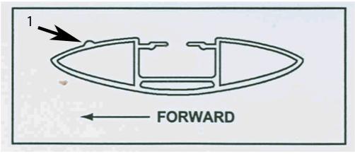
The roof rack cross rails have a ridge (1) on the front edge to reduce wind noise concerns. If the roof rack cross rails are installed with the ridge facing rearward on the vehicle, this bead will not perform as designed. Inspect the roof rack cross rails and verify that both of the cross rails are installed on the vehicle with the ridge facing forward on the vehicle. If the rails are improperly installed, reposition the cross rails with the ridges facing forward on the vehicle.
Subject: Wind Noise / Humming Noise from Roof Rack Area (Reposition Roof Rack Cross Rails)
Models: 2006-2010 Chevrolet HHR with Dealer Installed Accessory Roof Rack Cross Rails
--------------------------------------------------------------------------------
Condition/Concern:
Some customers may comment that they hear a wind noise or a humming noise coming from the roof rack area of the vehicle. This condition is most noticeable between 55-110 km/h (35-70 mph). This condition may be caused by the roof rack cross rails being installed backwards on the vehicle.
Recommendation/Instructions:
The roof rack cross rails have a ridge (1) on the front edge to reduce wind noise concerns. If the roof rack cross rails are installed with the ridge facing rearward on the vehicle, this bead will not perform as designed. Inspect the roof rack cross rails and verify that both of the cross rails are installed on the vehicle with the ridge facing forward on the vehicle. If the rails are improperly installed, reposition the cross rails with the ridges facing forward on the vehicle.
Last edited by ChevyMgr; 03-03-2010 at 01:07 PM.
03-04-2010, 06:56 PM
#129
Founding Member
Thread Starter
Join Date: 11-23-2007
Location: Texas
Posts: 8,210
Pic3956e
#PIC3956E: Red Brake Light/Low Brake Fluid Message On Intermittently - keywords C0267 DIC display GMT001 information int intermittent lamp PIC3959 PIC3959A PIC3959B - (Nov 16, 2007)
Subject: Red Brake Light/Low Brake Fluid Message On Intermittently
Models: 2006 Chevrolet HHR
--------------------------------------------------------------------------------
The following diagnosis might be helpful if the vehicle exhibits the symptom(s) described in this PI.
Condition/Concern:
A customer may comment about a intermittent RED brake light coming on with a possible message on the Driver Information Center (DIC) displaying "low brake fluid". This condition is more likely to occur during cold weather and will be intermittent as the fluid is more viscous
Recommendation/Instructions:
Follow the diagnostics to check and make sure that the brake fluid is not low. If the brake fluid is NOT low then replace the brake Master Cylinder Brake Fluid Reservoir KIT (P/N below) as it has been modified to resolve this concern.
Automatic Transmission Should be MN5 Auto Transmission Master Cylinder Brake Fluid Reservoir KIT Part # 15939572
Manual Transmission Should be M86 5-Sp Manual Transmission Master Cylinder Brake Fluid Reservoir KIT Part # 15939485
03-06-2010, 02:10 PM
#130
Founding Member
Thread Starter
Join Date: 11-23-2007
Location: Texas
Posts: 8,210
#06-07-30-004E: Various Concerns with Shifter and/or Ignition key (Perform Repair as Outlined) - (Mar 1, 2010)
Subject: Various Concerns With Shifter and/or Ignition Key (Perform Repair as Outlined)
Models: 2005-2010 Chevrolet Cobalt
2006-2010 Chevrolet HHR
2005-2006 Pontiac Pursuit (Canada Only)
2007-2010 Pontiac G5
with Automatic Transmission 4T45-E (RPO MN5)
--------------------------------------------------------------------------------
This bulletin is being revised to add the 2010 model year and include an Important statement on initial inspections to perform. Please discard Corporate Bulletin Number 06-07-30-004D (Section 07 - Transmission/Transaxle).
--------------------------------------------------------------------------------
Important: When servicing a vehicle for any type of shifter/key concern, please perform the following initial inspections prior to replacing any parts.
� Verify the electrical operation of the ignition lock cylinder solenoid. Refer to the Ignition Key Can/Cannot Be Turned Off With Transmission in Any Gear in SI.
� Verify the adjustment of the automatic transmission shift cable. Refer to the Shift Control Cable Adjustment procedure in SI.
� If these initial inspections do not resolve the customer concern, check the potential causes listed in this bulletin.
Condition #1 (2005-2008 Cobalt, G5 and Pursuit Only)
Some customers may comment that the shifter binds.
Cause #1
The cause of this condition may be the shifter button sticking in the handle.
Correction #1
Verify that the shifter button is inoperative by evaluating if the park pawl pin on the shifter assembly moves when activating the button. If the parking pawl does not move when the button is activated, the shifter handle will have to be replaced. Refer to Floor Shifter Control Knob Replacement in SI.
Parts Information #1 Part Number Description Qty
22706231 Handle, A/Trans Cont Lvr (Model AL with MN5, TY8, VY7) 1
22706232 Handle, A/Trans Cont Lvr (Model AJ, AK and MN5; Model AL with MN5 [exc VY7]) 1
22719080 Handle, A/Trans Cont Lvr (Model AL with MN5, VY7 [exc TY8]; Model AM with MN5; Model AL with MN5, R1V) 1
Condition #2 (2005-2008 Cobalt, G5 and Pursuit Only)
Some customers may comment they cannot remove the ignition key.
Cause #2
The pin that activates the micro-switch may have moved out of position (refer to illustration above). This causes the micro-switch to fail to engage when the vehicle is placed in Park. If this condition is present, the customer will not be able to remove the key from the ignition.
The illustration above shows the switch in a correct position.
Correction #2
Important: A change has been made to the shifter assembly for service. The replacement shifter assembly will read PRNDIL (Park, Reverse, Neutral, Drive, Intermediate and Low).
Verify that the micro switch is out of position. Replace the shifter assembly. Refer to Transmission Control Replacement in SI.
Parts Information #2 Part Number Description Qty
15926820 Control Asm, A/Trans 1
Condition #3 (2005-2008 Cobalt, G5 and Pursuit Only)
Some customers may comment that the shifter is hard to move.
Cause #3
The slider may be binding in the guides. This may cause the shifter to become difficult to operate.
Correction #3
Replace the slide indicator and guides in the shifter following the procedure below:
Apply the parking brake.
Remove the upper console trim. Refer to Trim Plate Replacement-Console Front in SI.
Remove shifter knob. Refer to Floor Shifter Control Knob Replacement in SI.
Remove the indicator plate. Use a flat-bladed screwdriver to release the locking tabs.
Remove the shifter indicator lens.
Pull up on the indicator and remove it from the assembly.
Remove the two front rails by unsnapping the front and lifting up, and then back, to remove the rails from the shifter assembly.
Install the new guides. Place the hook end into the assembly and push down. It will snap into place.
Install the new slide indicator. With the transmission in neutral, place the slide over the shifter and into the guides. Move the slide indicator down the guides in the front and rear.
Important: Replace the shifter indicator lens if damage is present due to the slider binding or if it becomes damaged during disassembly.
Install the shift indicator lens.
Install the shift indicator plate.
Install the shifter knob. Refer to Floor Shifter Control Knob Replacement in SI.
Install the upper console trim. Refer to Trim Plate Replacement-Console Front in SI.
Parts Information #3
Part Number Description Qty
15872229 Slide Indicator 1
15872228 Guide - Rails 2
15872230 Lens 1
Condition #4
Some customers may comment that the ignition key cannot be removed from the ignition cylinder.
Correction #4
Check for power and ground in the ignition circuit. Verify for proper connection/contact at circuit B1, connector X4 at the BCM.
Condition #5 (All Years, All Models)
Some customers may comment that the ignition key is difficult to remove or that the key sticks or binds in the ignition cylinder.
Correction #5
Refer to Corporate Bulletin Number 09-02-35-005A for additional information.

