Installing an Oil Catch Can
#361
My old gallery never made it back here after the system reset, and I had deleted all of them from my hard drive. But they are still in my posts, so that's something at least.
EDIT: The config I am running is just a few posts down.
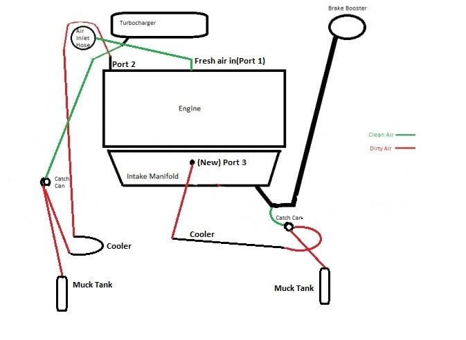
I have added the homemade muck collection tanks, plumbed into the bottom of the catch cans. More recently, I plumbed in the inline coolers.
What do you mean by extra catch cans?
I can't believe it's been nearly 2 years since I started participating in this science experiment!!
Last edited by RJ_RS_SS_350; 12-15-2017 at 01:03 PM.
#365

#367
09 HHR SS. I bought a new stock intake manifold a while back. When i pulled out the so called PCV valve that came with the new manifold to see what it was, i found it was just an air restrictor and there is no valve, no one way action. I checked the old one and it seem to be the same. After all this writing im still confused. So i need two catch cans and block or somehow re rout the worthless valve in the manifold? Also the pipe from the Turbo to the valve cover , is the air coming from the Turbo to the cover or from the cover to the Turbo?
#369
09 HHR SS. I bought a new stock intake manifold a while back. When i pulled out the so called PCV valve that came with the new manifold to see what it was, i found it was just an air restrictor and there is no valve, no one way action. I checked the old one and it seem to be the same. After all this writing im still confused. So i need two catch cans and block or somehow re rout the worthless valve in the manifold? Also the pipe from the Turbo to the valve cover , is the air coming from the Turbo to the cover or from the cover to the Turbo?
The dirty air moves from the valve cover(crankcase) to the turbo. It's a venturi effect when the turbo is spinning and moving a lot of air.
Here is the condensed version of the project. https://www.chevyhhr.net/forums/2-0l...version-59726/
#370
I copied this from a hot rod forum I belong to:
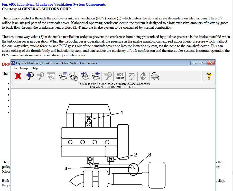
The PCV valve is a spring-loaded valve with a specific orifice size designed to restrict the amount of air that's pulled from the crankcase into the intake manifold. This is necessary because air drawn through the valve from the crankcase has a leaning effect on the fuel mixture, the same as a vacuum leak. So airflow through the valve must be controlled within certain limits. At idle, air flow is reduced because little blow-by is produced. When the engine is cruising and vacuum is high, airflow through the PCV valve is at the maximum to purge the blow-by vapors from the crankcase. It's important to note that PCV valves are sized for specific engine applications. The wrong PCV valve for an application can flow too much or too little air causing drive-ability problems.
When I do my catch can this summer I would like to use this valve because of the two barbed ends but can't find flow info on it.
https://www.ebay.com/itm/Toyota-Supr...-/200997596549
Unless there is another motor company that has a part like this design.


