Building an oil catch can for the SS
 08-07-2015, 06:42 PM
#1
Senior Member
Thread Starter

Join Date: 08-03-2010
Location: Lake Ronkonkoma, N.Y.
Posts: 3,564
Building an oil catch can for the SS
Hi
OK I'm ready. Going to build another catch can. Here is it's theory:
http://www.zhpmafia.com/forums/attac...2&d=1344887158
It's very simple. Will buy a "junk" separator from ebay install stainless mess and baffle plate with a tube.
I will only be hooking it up to the line that runs from valve cover to turbo, the other line will still be functional.
My main concern is it's location so there is easy access to drain it.
Thanks
 08-08-2015, 08:04 AM
#2
Senior Member
Thread Starter
Join Date: 08-03-2010
Location: Lake Ronkonkoma, N.Y.
Posts: 3,564
Update:
I found this on Ebay which I'm buying
Black Cylinder Style Car Racing Engine Oil Catch Tank Can Reservoir Hose | eBay
It looks like I can take it apart to install the mesh, baffle plate and tube. If anything is in it I'll be shocked.
It's dimensions are about the same size as a soda can, a can is 3"x5" the catch can is 3"x6".
I can use a soda can to see where placement would be the best for easy access to the drain on the can.
P.S.
Just ordered the can. It's being sent from China, will take a little time to get it because it has to pass customs. Will get it maybe in 8 days, from there I'll post pictures of my build.
P.S.S.
Just found this, as it's basically what I'm going to build:
http://forums.neons.org/viewtopic.php?f=8&p=3385063
Last edited by Cat Man HHR; 08-08-2015 at 08:44 AM.
08-09-2015, 07:42 AM
#3
Senior Member

Join Date: 09-07-2008
Location: Mebane, NC
Posts: 1,016
Cat Man HHR, thanks for the info. The price is right... I bought one myself. I made them for my truck and my 94 Impala SS. I got a Air filter from Northern tool and modified it. I tapped the center of the housing 3/8" NPT, got a 6" nipple from Lowes, drill a number of holes in it. Made some baffles and made the filtering from bulk furnace filter material. For it to work correctly air flow through the filter is reverse.
On my truck I need to empty it about every 3K miles, it's certainly not full but it will generally have about 1 to 1-1/2" of liquid in it. It worse in the winter, water vapor will condense in it as well. One would be surprised about the amount of oil/water it catches.
It's been my experience that any of the intake manifold that has a dip/valley that is below the intake port generally has a small pool oil in from the PCV system. My guess is that at low speed the oil vapor condenses falls out of suspension and pools at the lowest point, the bottom of the intake.
10-11-2015, 09:11 AM
#4
Senior Member
Thread Starter
Join Date: 08-03-2010
Location: Lake Ronkonkoma, N.Y.
Posts: 3,564
Sorry it's taken so long but this is what I did.
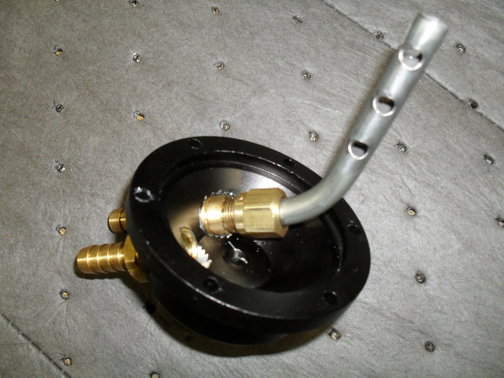
Took the above mentioned Ebay oil catch can I bought and using brass 3/8 npt to 3/8 nipples I installed them to the top lid with a 1/4 npt compression fitting for 3/8 tube tapped into one fitting. Had to grind down the hex on that fitting to pass thru the tapped hole on the lid. Added the steel 3/8 pipe to the fitting and added a few vent holes. More than likely this step could have been done with JB Weld.
I then bought this
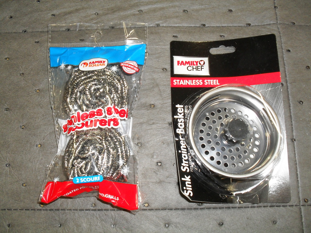
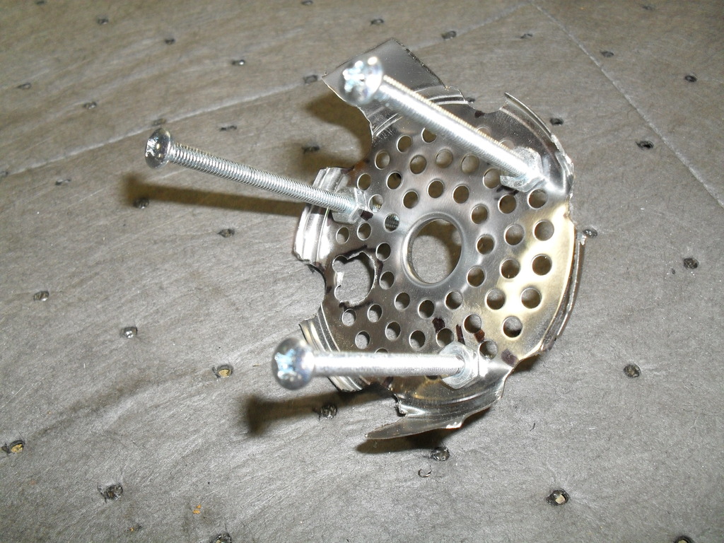
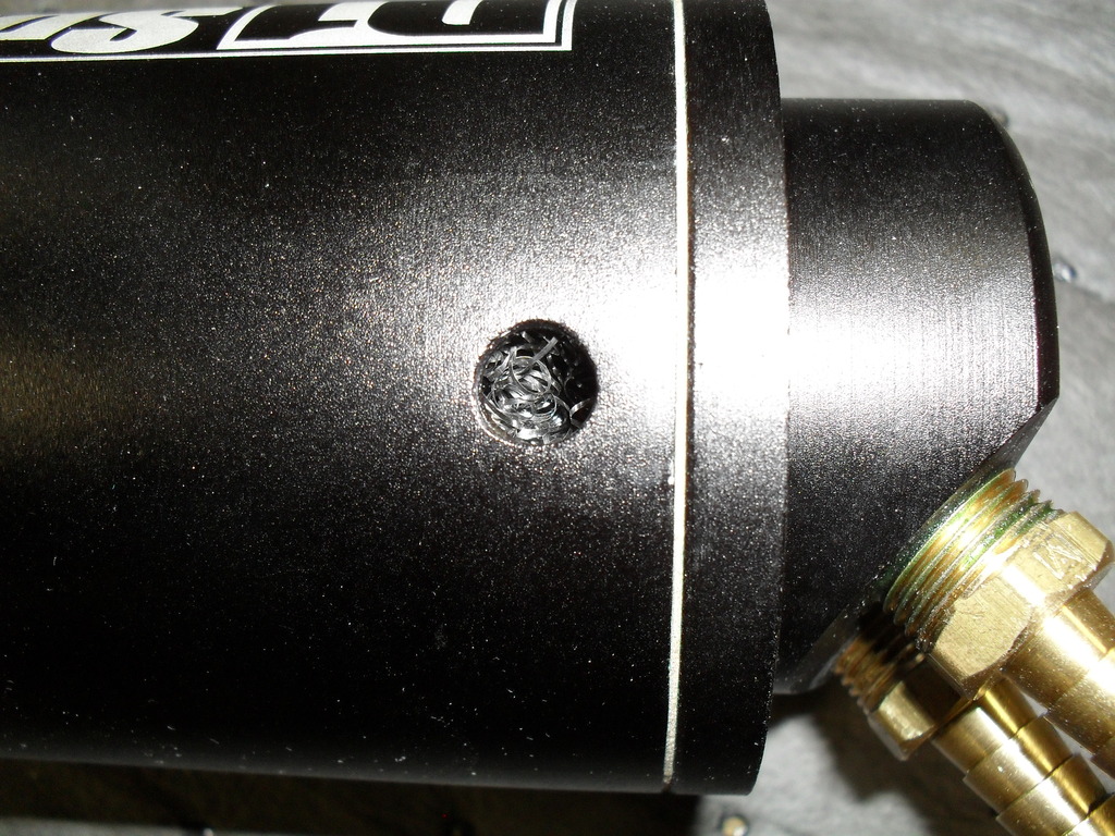
Cut up the drain screen and added legs to it using 8/32 x 3" machine screws that made the screen sit 2" from the bottom of the can and a hole for the vent down pipe to fit
Install the wire mesh/baffle plate and put the bottom lid on
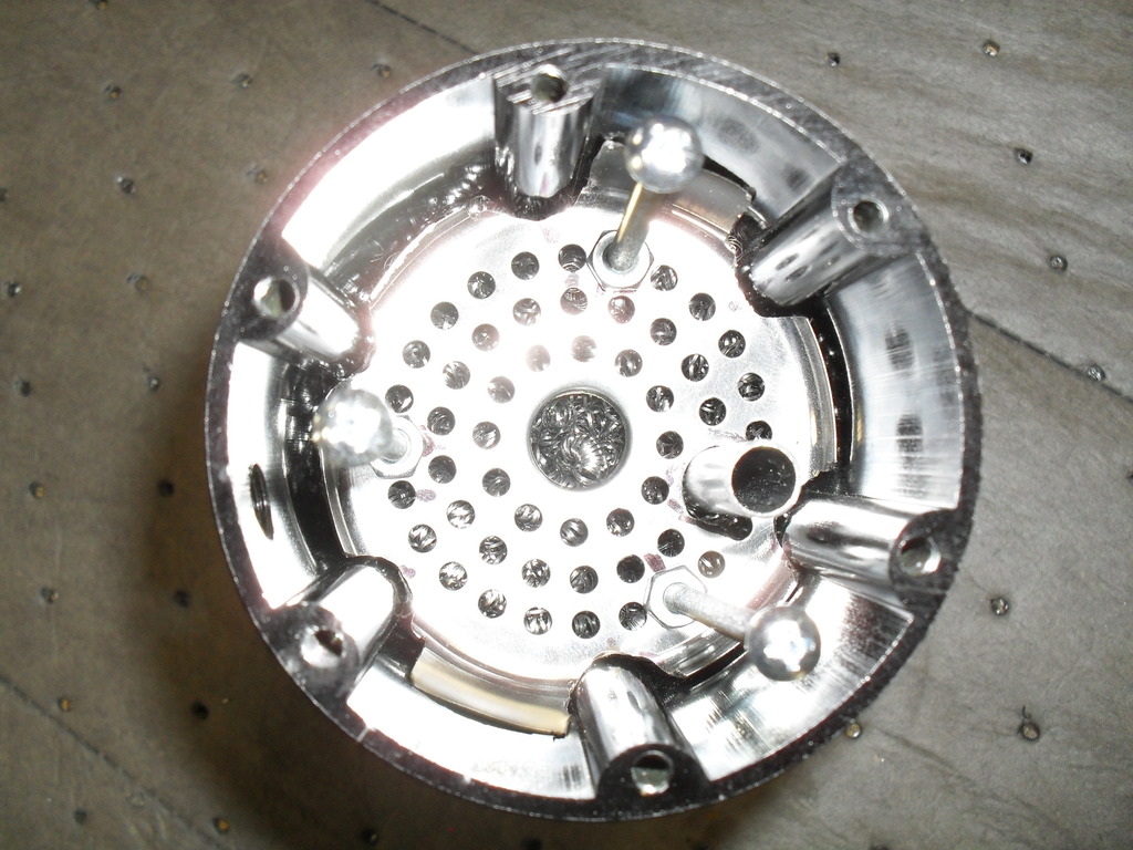
So now the bottom hole of the sight glass hole was clear (the vent pipe is also long enough to go passed the baffle plate)
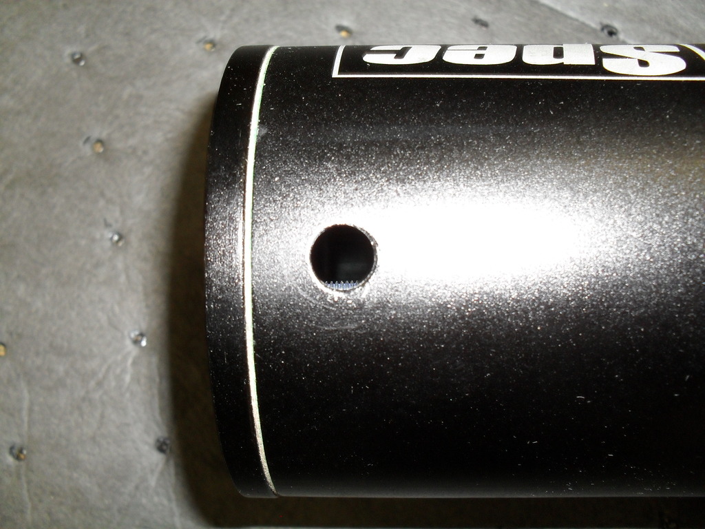
And the top hole has mesh
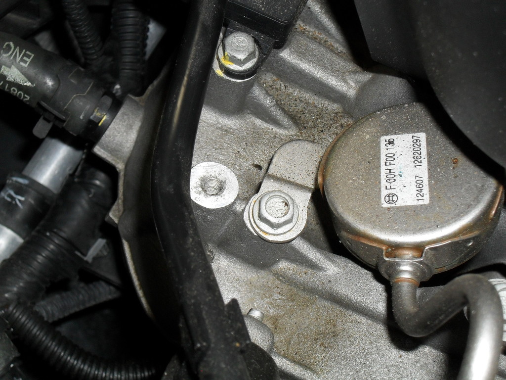
After adding the sight glass tube I found a spot on the intake for bolt (6mx1x12) and a home made L bracket
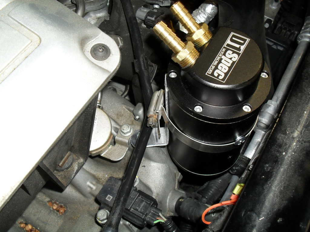
Installed the catch can (this is the first L bracket made from aluminium which was later made from steel) also you can see one of the mounting screws supplied with the catch can, this help stop the can from sliding down
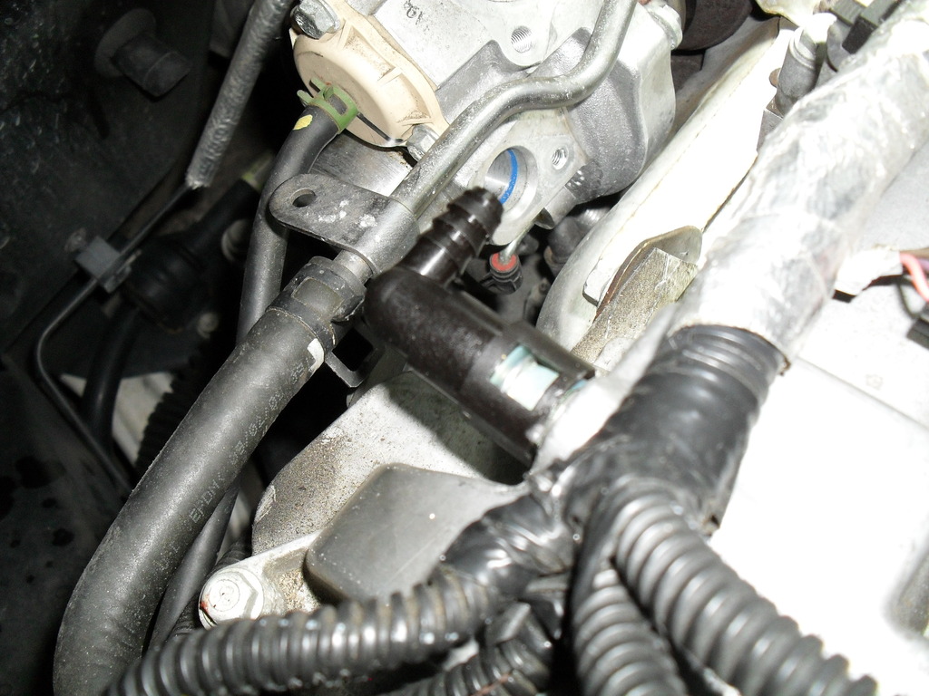
OK now onto this, I tried to make a release tool out of air brake plastic tubing but it didn't work. So for everybody just to know, cut it off on both ends. Cut carefully just at the lip all the way around it.
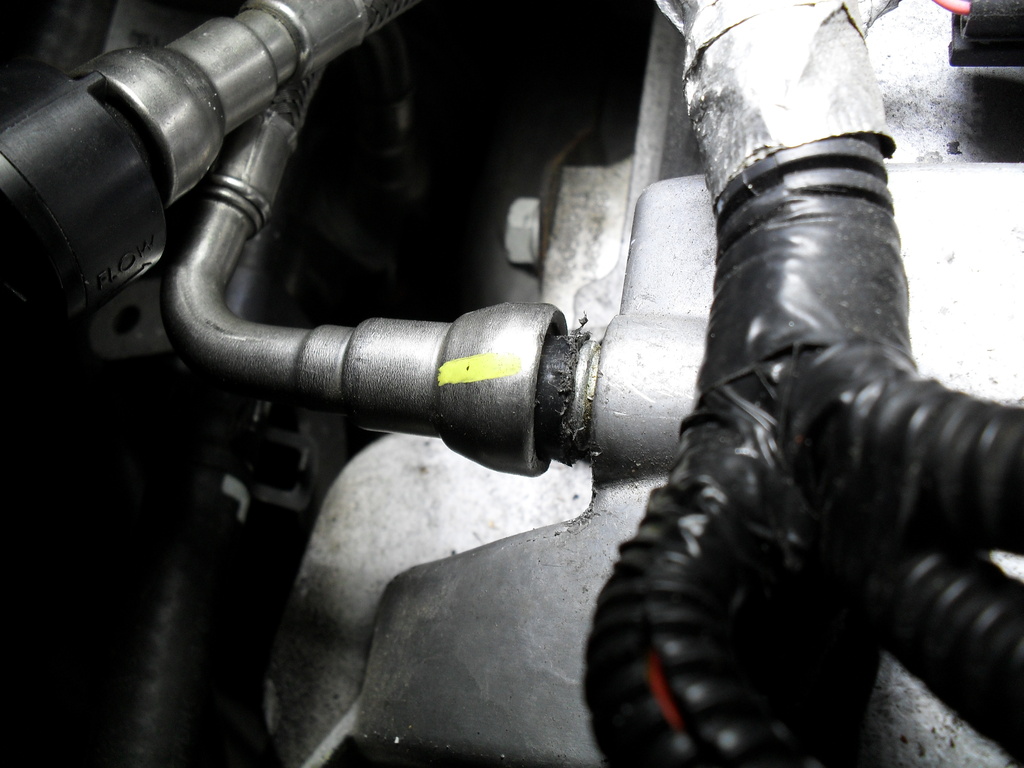
The end by the turbo can be taken out by first removing the retainer bolt and then using a flat blade screw driver, insert it at the front of the plate and twist while pulling on the hose. I bought this from Dorman for the nipple at the valve cover the part comes two to a package
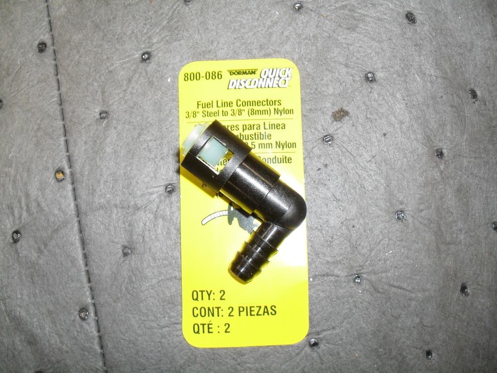
To make it connect to the shorty nipple on the valve cover the outer white plastic wings have to be removed
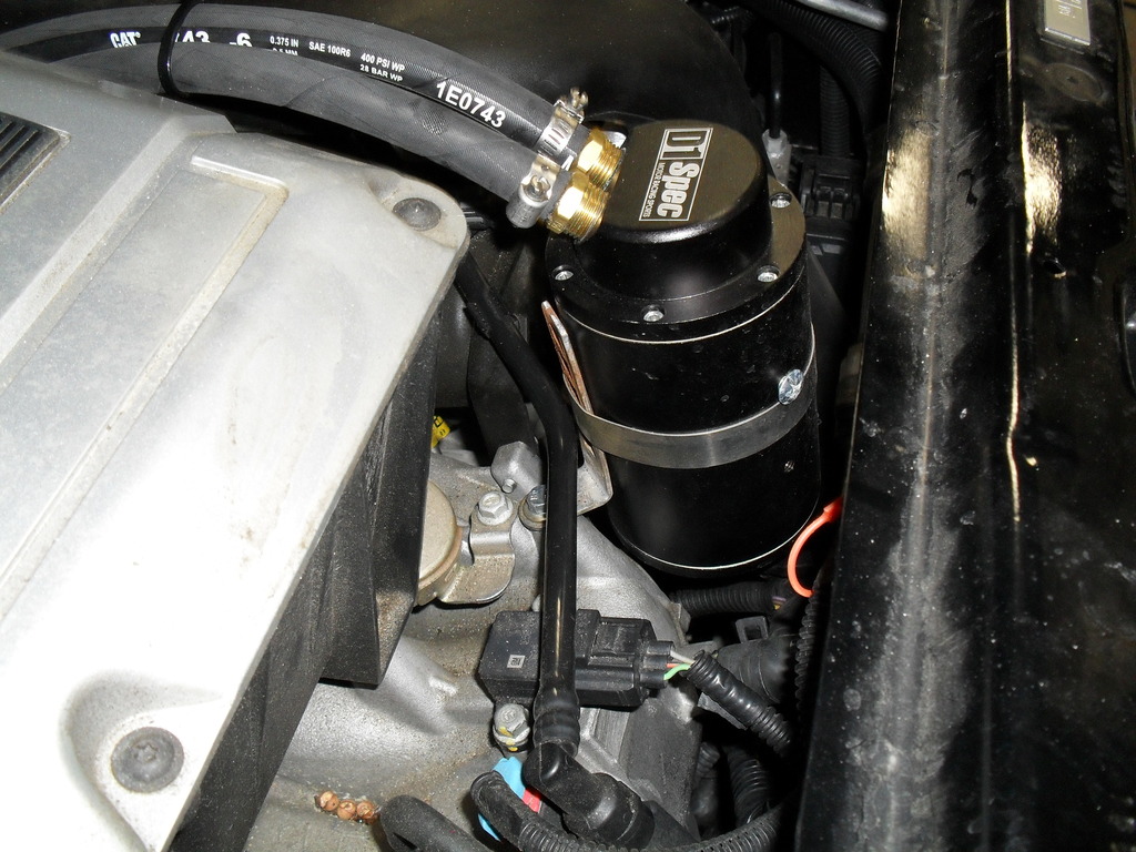
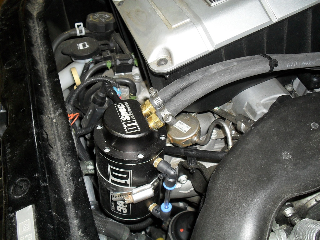
Once that's done install the hose's. As you can see I'm using my stock air box. The can blocks getting to the oil filter but can be taken out of the way to do a filter change. Also the can be lifted to remove it's drain plug when needed.

Took the above mentioned Ebay oil catch can I bought and using brass 3/8 npt to 3/8 nipples I installed them to the top lid with a 1/4 npt compression fitting for 3/8 tube tapped into one fitting. Had to grind down the hex on that fitting to pass thru the tapped hole on the lid. Added the steel 3/8 pipe to the fitting and added a few vent holes. More than likely this step could have been done with JB Weld.

I then bought this

Cut up the drain screen and added legs to it using 8/32 x 3" machine screws that made the screen sit 2" from the bottom of the can and a hole for the vent down pipe to fit

Install the wire mesh/baffle plate and put the bottom lid on

So now the bottom hole of the sight glass hole was clear (the vent pipe is also long enough to go passed the baffle plate)

And the top hole has mesh

After adding the sight glass tube I found a spot on the intake for bolt (6mx1x12) and a home made L bracket

Installed the catch can (this is the first L bracket made from aluminium which was later made from steel) also you can see one of the mounting screws supplied with the catch can, this help stop the can from sliding down

OK now onto this, I tried to make a release tool out of air brake plastic tubing but it didn't work. So for everybody just to know, cut it off on both ends. Cut carefully just at the lip all the way around it.

The end by the turbo can be taken out by first removing the retainer bolt and then using a flat blade screw driver, insert it at the front of the plate and twist while pulling on the hose. I bought this from Dorman for the nipple at the valve cover the part comes two to a package

To make it connect to the shorty nipple on the valve cover the outer white plastic wings have to be removed

Once that's done install the hose's. As you can see I'm using my stock air box. The can blocks getting to the oil filter but can be taken out of the way to do a filter change. Also the can be lifted to remove it's drain plug when needed.


Last edited by Cat Man HHR; 10-11-2015 at 10:21 AM.
10-12-2015, 09:25 AM
#5
Senior Member
Join Date: 09-07-2008
Location: Mebane, NC
Posts: 1,016
I can't tell for sure and to be clear, you placed your catch can in between the line that runs from the valve cover and the inlet to the turbo itself, correct? The line running from the air inlet tube running from the air box to the valve cover remains the same?
If that indeed is the case, doing what you did will stop or lessen the amount of oil mist that is drawn into the turbo inlet itself and pushed through the hot side charge pipe, intercooler, cool side charge pipe, throttle body. That breather line is intended draw any by-pass pressure when you are in boost.
The next one you have to attack is the one in intake manifold. The PCV valve itself is mounted in the manifold and draws any crank case by-pass pressure when you not in boost mode, i.e. idel, decel, high vacuum condition. That is going to be more challenging. As I see it you will have to remove the intake plug one hole and then drill and tap for a fitting that will re-route the crank case by-pass oil vapor out to another catch can and then back to the intake manifold either by connecting to the brake booster line, or drilling and tapping for another fitting.
I am going to design and machine a fitting of sorts that will hold the factory PCV valve that was removed from the intake manifold and can be connected in the hose that would be running from the new intake vacuum fitting and catch can. I know some of your are probably thinking why not just get and use a different PCV Valve... well the one removed from the intake manifold is a positive seal when pressurized from the intake side, i.e. boosting. Some of the other inline PCV valves I have seen are not a positive seal when pressurized on reverse side and that being the case one of the last thing you want to do is add any pressure the the crank case..... you wont like the results.
10-13-2015, 05:53 PM
#6
Senior Member
Thread Starter
Join Date: 08-03-2010
Location: Lake Ronkonkoma, N.Y.
Posts: 3,564
My intent was to stop or slow down the oil vapor fumes entering the inlet to the turbo's compressor wheel.
I have in the past worked on Caterpillar 3208 turbo boat engines and that system vents crankcase pressure fumes right into the turbo inlet. With heat and time the compressor wheel starts to gum up and slows down causing a lower boost psi then factory spec. As a maintenance to this you would take off the compressor housing and clean off the build up of oil on the wheel and housing using brake clean.
My engine has 28K on it and with a mirror I saw an oil film on the compressor wheel, not much, but it was there. It didn't really show any build up in the IC hot pipe. I did spray brake clean on it to flush any residue that was there. I'm using synthetic oil also.
Never considered the PCV system. I can see where intake manifold vacuum is present but I wounder how much vs the vacuum made at the turbo inlet running down the road. I did install an OEM pillar analog boost gauge and do see vacuum readings now and yes vacuum is very high at idle but starts to go towards positive pressure as you drive. I wish I could data log manifold vacuum vs turbo inlet vacuum vs time.
Dr. Loch could possibly show a diagram of your design?
 12-06-2018, 01:26 PM
#8
Senior Member

Join Date: 01-16-2017
Location: Ohio
Posts: 360
@DrLoch, did you come up with a plan for the intake PCV connection?
12-06-2018, 03:25 PM
#9
Senior Member
Thread Starter
Join Date: 08-03-2010
Location: Lake Ronkonkoma, N.Y.
Posts: 3,564
I'm sorry but I never followed up with the catch can I made. Having to use the car as a daily driver has limited me to repairs that would lay the car up.
Any way you can collect oil vapor that is not ment to be on your intake valves is a plus.
Why the engineers that designed this engine put a PCV valve inside the intake manifold is beyond me.
Any way you can collect oil vapor that is not ment to be on your intake valves is a plus.
Why the engineers that designed this engine put a PCV valve inside the intake manifold is beyond me.
12-06-2018, 06:49 PM
#10
Senior Member
Join Date: 01-16-2017
Location: Ohio
Posts: 360
I'm sorry but I never followed up with the catch can I made. Having to use the car as a daily driver has limited me to repairs that would lay the car up.
Any way you can collect oil vapor that is not ment to be on your intake valves is a plus.
Why the engineers that designed this engine put a PCV valve inside the intake manifold is beyond me.
Any way you can collect oil vapor that is not ment to be on your intake valves is a plus.
Why the engineers that designed this engine put a PCV valve inside the intake manifold is beyond me.

Thread
Thread Starter
Forum
Replies
Last Post