
Install 1999 Chevy Blazer OverHead Console


Thread Starter
New Member
Joined: 03-26-2017
Posts: 25
From: SF Bay Area
Install 1999 Chevy Blazer OverHead Console
Okay, here goes nothing...
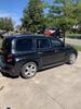
I found the long 1999 Chevy Blazer OHC at a local a salvage yard for $8. The interior of my HHR is ebony, with a light gray (almost white) ceiling. So the ebony OHC matched nicely with my interior.
If I had to do it again, I would also pull the mounting brackets, if they exist. Some models contain them, some don't. As such, I ended up fabricating my own mounting system. But more on that, later.
Once I found the console, I needed to figure out the wiring. I wanted to hook things up before even trying to mount it.

OHC/Rear View Mirror Display, and Cabin Temp Sensor

Cabin Temp Sensor

Hmmm... that's it for now. Am sure I missed stuff but will happily answer any questions, if I did.
I found the long 1999 Chevy Blazer OHC at a local a salvage yard for $8. The interior of my HHR is ebony, with a light gray (almost white) ceiling. So the ebony OHC matched nicely with my interior.
If I had to do it again, I would also pull the mounting brackets, if they exist. Some models contain them, some don't. As such, I ended up fabricating my own mounting system. But more on that, later.
Once I found the console, I needed to figure out the wiring. I wanted to hook things up before even trying to mount it.
This series (1990-1999) console has two harnesses, one for the courtesy light and the front/rear map/reading lights, and the other for the LED display.
The first harness, the lights connector, has four wires, two hot and two ground. The orange and the yellow/purple wire were for the map/reading lights. The factory installed overhead lights have a three wire harness (red [12V], black[GND] and grey[Courtesy]). Which basically means, wire the 12V & GND to the orange and yellow/purple. And wire the 12V & Courtesy to the remaining two wires. You need to test these to ensure you have run them correctly. That is, polarity is important, here. If you have, the courtesy light will turn on when you open the door and automatically turn off after 9 seconds. The remaining map/reading lights require pushing the off/on button by each light.
The second harness, the LED display connector comes in two flavors. One is a 9 pin harness for the console with the mode button for DIC info. And the other is a 6 pin harness for the console with the on/off button. The latter shows direction and temperature only. Mine is the latter.
To figure out the above, I relied upon the following.
As an fyi, I only wired the first four LED wires (power, ground, vss, & temp sensor).
While the temp sensor is for the outside ambient air temperature sensor (generally near the grill, or in the HHR case, under the passenger side fender behind the headlight), I decided to use a separate temperature probe (which I installed above the driver side area) to read cabin temp. This involved repurposing an LED ceiling receptacle that I pulled from a 2008 HHR telematics setup, and replacing the LED with a 10K ohm/5% variance NTC thermistor. The LED receptacle harness had two wires (PWR/GND). In this case, I tied one wire to ground and the other to the "Ambient Air Temperature Sensor Signal". Polarity is irrelevant.
As for the VSS? I hooked that line to the blue/pink VSS wire from the AXXESS LC-GMRC-LAN-03 harness for hooking up my Pioneer Head Unit.
I used the "Mini Add a Circuit" tapped into the sunroof fuse position in the BCM for 12V RAP power.
And ground is, of course, tied to ground.
Okay, so much for electrical. Next? Mounting the thing.The first harness, the lights connector, has four wires, two hot and two ground. The orange and the yellow/purple wire were for the map/reading lights. The factory installed overhead lights have a three wire harness (red [12V], black[GND] and grey[Courtesy]). Which basically means, wire the 12V & GND to the orange and yellow/purple. And wire the 12V & Courtesy to the remaining two wires. You need to test these to ensure you have run them correctly. That is, polarity is important, here. If you have, the courtesy light will turn on when you open the door and automatically turn off after 9 seconds. The remaining map/reading lights require pushing the off/on button by each light.
The second harness, the LED display connector comes in two flavors. One is a 9 pin harness for the console with the mode button for DIC info. And the other is a 6 pin harness for the console with the on/off button. The latter shows direction and temperature only. Mine is the latter.
To figure out the above, I relied upon the following.

As an fyi, I only wired the first four LED wires (power, ground, vss, & temp sensor).
While the temp sensor is for the outside ambient air temperature sensor (generally near the grill, or in the HHR case, under the passenger side fender behind the headlight), I decided to use a separate temperature probe (which I installed above the driver side area) to read cabin temp. This involved repurposing an LED ceiling receptacle that I pulled from a 2008 HHR telematics setup, and replacing the LED with a 10K ohm/5% variance NTC thermistor. The LED receptacle harness had two wires (PWR/GND). In this case, I tied one wire to ground and the other to the "Ambient Air Temperature Sensor Signal". Polarity is irrelevant.
As for the VSS? I hooked that line to the blue/pink VSS wire from the AXXESS LC-GMRC-LAN-03 harness for hooking up my Pioneer Head Unit.
I used the "Mini Add a Circuit" tapped into the sunroof fuse position in the BCM for 12V RAP power.
And ground is, of course, tied to ground.
For starters, I cut a small square hole above the mirror for pulling the wiring harness through, and also for accessing the mounting area. And, I cut a 12" x 6" (longest part goes front to back) hole between the front seat belt pillars. Next was to install speedy "U" nuts.

Since I did not take pics, I doctored up a pic that lunchbox posted, as follows, for illustrating mounting positions:

I used 1 speedy nut in the front (see red arrow) and 4 speedy nuts (2 on each side of the metal hump) between the front seatbelt pillars. (see blue arrow)
The front of the OHC was anchored to the speedy nut with a 2" 10/20 bolt. I anchored a 12"x12" 1" piece of wood with 4 1�" 10/20 bolts to the 4 speedy nuts, and then screwed the back end of the console to that. To deal with the spacing, since the roof contour was different, I used small pipe insulation, cut in half, lengthwise, and used the adhesive to hold it to the ceiling long enough to screw in the OHC, which then compressed the foam.
Finished Product:Since I did not take pics, I doctored up a pic that lunchbox posted, as follows, for illustrating mounting positions:
I used 1 speedy nut in the front (see red arrow) and 4 speedy nuts (2 on each side of the metal hump) between the front seatbelt pillars. (see blue arrow)
The front of the OHC was anchored to the speedy nut with a 2" 10/20 bolt. I anchored a 12"x12" 1" piece of wood with 4 1�" 10/20 bolts to the 4 speedy nuts, and then screwed the back end of the console to that. To deal with the spacing, since the roof contour was different, I used small pipe insulation, cut in half, lengthwise, and used the adhesive to hold it to the ceiling long enough to screw in the OHC, which then compressed the foam.
OHC/Rear View Mirror Display, and Cabin Temp Sensor
Cabin Temp Sensor
Hmmm... that's it for now. Am sure I missed stuff but will happily answer any questions, if I did.
Last edited by Psicloned; May 23, 2017 at 03:36 AM. Reason: typos, etc.


Moderator
Joined: 05-01-2014
Posts: 8,511
From: California
Nice, thanks for posting Psicloned! So you cut the 12" x 6" (rectangular?) hole in the metal of the roof reinforcement? And where did the 12" x 12" wood go in relation to that cut?
And it seems you didn't have to cut the headliner or the OHC. Was the contour pretty close, or did the OHC compress the headliner, reinforced with the pipe insulation?
Really, looks pretty sharp!! Nice work!
And it seems you didn't have to cut the headliner or the OHC. Was the contour pretty close, or did the OHC compress the headliner, reinforced with the pipe insulation?
Really, looks pretty sharp!! Nice work!

Thread Starter
New Member
Joined: 03-26-2017
Posts: 25
From: SF Bay Area
Here's a photoshopped version...

The speedy nuts go on either side of the "metal hump with the slots." I used a drill stop to keep from drilling into the roof. I also drilled the holes with the wood in place. The holes were a larger diameter than the speedy nut hole. This allowed me to move the wood to one side and easily position the speedy nuts (which clipped over the edge of the metal) over the drilled holes. Then move the wood back. I used a "slim" screw driver to align the wood/speedy nut holes. At this point, I could simply screw in the bolts. This, btw, was my solution to dealing with "blind attachments," so to speak.
Anyway, hope this helps.
P.s. btw, I really couldn't stomach cutting the headliner so that the OHC pushed up inside it to the ceiling, as described by the one thread in the above links. My concern was that I would end up cutting too much. Which is why I did it the way I did.
Btw, this is the LED receptacle that I used... which I thought was from the telematics. But from that thread, it appears it wasn't.
Last edited by Psicloned; May 24, 2017 at 01:34 AM. Reason: typos, etc
Thread Starter
New Member
Joined: 03-26-2017
Posts: 25
From: SF Bay Area
I used bits and pieces of info from the above links. So, those were the links I intended. Though, it appears I missed an important link... the one with the cutout (as well as compass calibration info, see below). The primary reason I posted the links in the first place was to attribute the info originators.
Anyway, here's the link I missed.
Notably, his calibration description, while close, was not exact, as applied to my 1999 console. That is, when you hold the on/off - us/met buttons simultaneously for 5 seconds, the display read both var and cal, with the cal just below the var. You set the variance by pushing the us/met button until you reach the desired value. It will cycle around, if you go too fast and pass the desired value. Once you've reached the desired value, you push the on/off, which gets you back to the compass direction with the word cal, just to the left. After driving in circles, the cal eventually disappears, and you're all set.
That said, and all things considered wrt this project? Imho, the mounting of the console was the biggest challenge. Though, from where I sit, I suspect people can come up with various ingenious ways to mount the console that are way better than my jury rigged solution.
Anyway, here's the link I missed.
Complete Directions on installing the Astrovan Overhead ConSSole Mod
Variance Map for Compass Calibration

Variance Map for Compass Calibration
Notably, his calibration description, while close, was not exact, as applied to my 1999 console. That is, when you hold the on/off - us/met buttons simultaneously for 5 seconds, the display read both var and cal, with the cal just below the var. You set the variance by pushing the us/met button until you reach the desired value. It will cycle around, if you go too fast and pass the desired value. Once you've reached the desired value, you push the on/off, which gets you back to the compass direction with the word cal, just to the left. After driving in circles, the cal eventually disappears, and you're all set.
That said, and all things considered wrt this project? Imho, the mounting of the console was the biggest challenge. Though, from where I sit, I suspect people can come up with various ingenious ways to mount the console that are way better than my jury rigged solution.


Thread
Thread Starter
Forum
Replies
Last Post
Heartbeat
Appearance/Modifications Discussions
4
Aug 21, 2006 10:28 PM