Installing aftermarket Remote Keyless Entry
 08-12-2017, 03:38 PM
#1
New Member
Thread Starter

Join Date: 06-22-2017
Location: Alabama
Posts: 15
Hi guys! It's me again. (This guy: https://www.chevyhhr.net/forums/prob...program-59029/ )
So after hearing multiple times "It just won't program", I am taking matters into my own hands and installing an aftermarket RKE.
Now, I've got the wiring of the unit figured out. I need to find out what wires I need to hook into to simulate a press of the switch on the driver side door. From the wiring diagram I *think* I need to connect the lock to the white coming out of the door wiring harness and the unlock to the black/white.
Anyone have an idea?
Here's the wiring diagram for the door.
 08-12-2017, 03:59 PM
#2
Technical Moderator
Join Date: 01-23-2009
Location: Fredericksburg, Virginia
Posts: 24,672
Did you buy a RKE kit, there are many out there; Bulldog comes to mind. They come with direction.
When I installed one all I had to do was splice into one wire at the BCM and insert a resistor in another wire.
This site has directions posted on it.
Remote Car Starter & Keyless Entry Systems ? BulldogSecurity.com
Direct link to PDF
http://www.bulldogsecurity.com/manua...0ManualLOW.pdf
It is not as simple as pretending to push the button.
On Ebay: Universal Car Remote Central Kit Keyless Entry System with Remote Controllers E1 | eBay
Last edited by RJ_RS_SS_350; 08-12-2017 at 05:44 PM. Reason: Fixed link to PDF
 08-12-2017, 04:09 PM
#3
Technical Moderator
Join Date: 01-23-2009
Location: Fredericksburg, Virginia
Posts: 24,672
And it turned out, after I got the dealership to admit they were just stupid and they programmed the RCDLR, it worked along side.
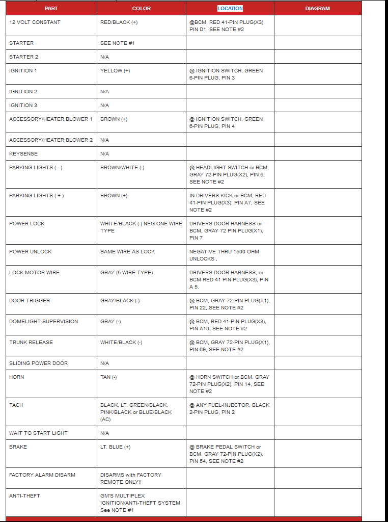
It's a 1.5K resistor in the wire on pin#7 on the BCM X1 connector Wht/blk.
Here is more from Buldog:

It's a 1.5K resistor in the wire on pin#7 on the BCM X1 connector Wht/blk.
Here is more from Buldog:
 08-12-2017, 04:33 PM
#4
Moderator

Join Date: 05-01-2014
Location: California
Posts: 7,791
Hi guys! It's me again. (This guy: https://www.chevyhhr.net/forums/prob...program-59029/ )
So after hearing multiple times "It just won't program", I am taking matters into my own hands and installing an aftermarket RKE.
Now, I've got the wiring of the unit figured out. I need to find out what wires I need to hook into to simulate a press of the switch on the driver side door. From the wiring diagram I *think* I need to connect the lock to the white coming out of the door wiring harness and the unlock to the black/white
It seems more likely that you want the wires that go to the latches(or maybe the relays?), not the switches. But I have to admit, this system is difficult to understand.
08-12-2017, 05:22 PM
#5
Administrator
Join Date: 10-13-2011
Location: Welland,Ont Canada
Posts: 36,460
08-12-2017, 05:30 PM
#6
New Member
Thread Starter
Join Date: 06-22-2017
Location: Alabama
Posts: 15
Did you buy a RKE kit, there are many out there; Bulldog comes to mind. They come with direction.
When I installed one all I had to do was splice into one wire at the BCM and insert a resistor in another wire.
This site has directions posted on it.
http://www.bulldogsecurity.com/manua... ManualLOW.pdf
It is not as simple as pretending to push the button.
On Ebay: Universal Car Remote Central Kit Keyless Entry System with Remote Controllers E1 | eBay
Here's the unit I got:
08-12-2017, 05:30 PM
#7
Technical Moderator
Join Date: 01-23-2009
Location: Fredericksburg, Virginia
Posts: 24,672
It only looks complicated; it is only 1 wire: G to 1500Ohms is unlock and over 1500 ohm is lock on the ground wire.
Once again we are getting confused between distribution diagrams and wiring schematics.
I think 2006 is actually a wht wire. Note the resistor in the switch.
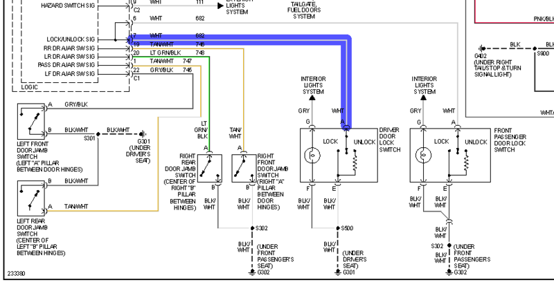
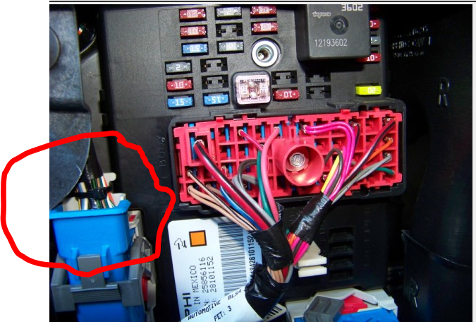
So you splice the lock wire from your control unit directly into the white wire and the unlock from the control unit to a 1.5K resistor to the same point.
No need to go into the door panel, the wires are right there at the BCM connector X1. Lots of room to hide the control unit.
IIRC in this bundle
Once again we are getting confused between distribution diagrams and wiring schematics.
I think 2006 is actually a wht wire. Note the resistor in the switch.

So you splice the lock wire from your control unit directly into the white wire and the unlock from the control unit to a 1.5K resistor to the same point.
No need to go into the door panel, the wires are right there at the BCM connector X1. Lots of room to hide the control unit.
IIRC in this bundle
08-12-2017, 05:32 PM
#8
New Member
Thread Starter
Join Date: 06-22-2017
Location: Alabama
Posts: 15
Doesn't seem right. My diagram in Haynes is a little different, but one thing that is the same, is that blk/wht is always grounded. So if you want that wire grounded, then you could hook to the blk/wht.
It seems more likely that you want the wires that go to the latches(or maybe the relays?), not the switches. But I have to admit, this system is difficult to understand.
It seems more likely that you want the wires that go to the latches(or maybe the relays?), not the switches. But I have to admit, this system is difficult to understand.
08-12-2017, 05:36 PM
#9
New Member
Thread Starter
Join Date: 06-22-2017
Location: Alabama
Posts: 15
It only looks complicated; it is only 1 wire: G to 1500Ohms is unlock and over 1500 ohm is lock on the ground wire.
Once again we are getting confused between distribution diagrams and wiring schematics.
I think 2006 is actually a wht wire. Note the resistor in the switch.
Attachment 45418
Once again we are getting confused between distribution diagrams and wiring schematics.
I think 2006 is actually a wht wire. Note the resistor in the switch.
Attachment 45418
08-12-2017, 05:56 PM
#10
New Member
Thread Starter
Join Date: 06-22-2017
Location: Alabama
Posts: 15
It only looks complicated; it is only 1 wire: G to 1500Ohms is unlock and over 1500 ohm is lock on the ground wire.
Once again we are getting confused between distribution diagrams and wiring schematics.
I think 2006 is actually a wht wire. Note the resistor in the switch.
Attachment 45418
So you splice the lock wire from your control unit directly into the white wire and the unlock from the control unit to a 1.5K resistor to the same point.
No need to go into the door panel, the wires are right there at the BCM connector X1. Lots of room to hide the control unit.
IIRC in this bundle
Attachment 45419
BTW, a metric ton of thanks for all you folks' help!!