
Vacuum tank fail


Member
Joined: 10-11-2014
Posts: 51
From: nc
Vacuum reservoirs allow operation of the power brakes and other vacuum operated accessories when sufficient engine vacuum isn't present (I.e when boosting or you're on the throttle at all). You'll probably want to reattach that.

Platinum Member
Joined: 12-06-2009
Posts: 11,719
From: Alabama
Member
Joined: 10-11-2014
Posts: 51
From: nc
Member
Joined: 10-11-2014
Posts: 51
From: nc
Well, I'll revise my statement, but only in terms of the pcv bit which was my bad for looking at a photo and not opening the hood on my car. The brake booster and both vacuum reservoir lines all appear to be plumbed into the intake with what looks like a valve in line on the left most vacuum reservoir connection. I would still think that the function of the reservoir is to provide enough of a drop in manifold pressure so that the vacuum brakes booster can work correctly (i.e. faster than manifold pressure drops by itself when you let off the throttle). Should be simple enough for the OP to test. Drive under boost then quickly hit the brakes and see if they feel boosted or not.
Platinum Member
Joined: 12-06-2009
Posts: 11,719
From: Alabama
The brake booster is a reservoir. It can store vacuum because it has a check valve at the booster end of the hose.
Maybe in the old rod days of high lift,long duration cams you would need a storage reservoir because of no vacuum at low rpms. I don't think that's the case with the LNF engines.
Maybe in the old rod days of high lift,long duration cams you would need a storage reservoir because of no vacuum at low rpms. I don't think that's the case with the LNF engines.
Platinum Member
Joined: 12-06-2009
Posts: 11,719
From: Alabama
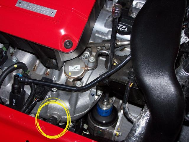
OK. Got curious and decided to look into what this vacuum canister is for. It is just for the bypass valve system on the turbo.
It is NOT part of the PCV or the brake booster vacuum.
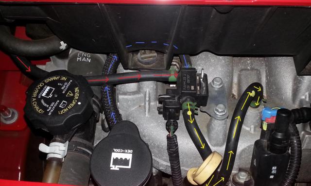
The picture below shows the vacuum hose routing and direction of vacuum pull.
Yellow: goes to and from the canister under the manifold.
Blue : is the hose to the lower charge pipe(nipple next to the lower Tmap sensor )
Red : is the hose to the bypass valve on the turbo
Now that valve that connects them together in the middle ? Not really sure how this works or functions.
It is NOT part of the PCV or the brake booster vacuum.
The picture below shows the vacuum hose routing and direction of vacuum pull.
Yellow: goes to and from the canister under the manifold.
Blue : is the hose to the lower charge pipe(nipple next to the lower Tmap sensor )
Red : is the hose to the bypass valve on the turbo
Now that valve that connects them together in the middle ? Not really sure how this works or functions.
Last edited by firemangeorge; Dec 17, 2014 at 07:42 PM.
