
Installing an Oil Catch Can


Moderator
Joined: 05-01-2014
Posts: 8,499
From: California
My intention is to make a machined fitting that will hold the original PCV and put it in the line going from the catch can back to the intake manifold. If you were to put the PCV valve in the line running from your new vapor pick off fitting and the catch can you would pressurizing the catch can.
I plan to run a 1/2" hose from a barb fitting on the catch can, grind a little bit of the lip off the PCV valve (where the O-ring is now), and clamp the 1/2" hose directly to the PCV valve. Then a 5/16" hose clamped directly to the small end of the PCV valve to a barbed tee in the booster hose.
I've got a question about the catch can, though. I've got one from Home Depot. (This pic is with the bowl off)

The slot on the bottom is connected to the "IN", and the hole in the middle , to the "OUT". So the "OUT" is inside the sintered brass cup. If i plumb it backwards, wouldn't the oil just pool up inside the cup, clogging it? I would have thought to plumb the dirty air into the bowl. Should I put some brass scotch-brite in the bowl?

Thread Starter
Senior Member
Joined: 05-29-2015
Posts: 542
From: Cleveland, OH
Yes the catch can will see boost pressure, but only as much as the pcv allows. I could install it on the output of the catch can, I don't really see the need. If boost pressure tries shoving dirty air back into the intake the pcv will only allow 10% of the volume. It will also be headed back into the galleys and not into my intake. Which is what I'm after in the first place.
The brake booster sees this under normal circumstances so I have nothing to worry about there.
The brake booster sees this under normal circumstances so I have nothing to worry about there.

Senior Member
Joined: 09-02-2010
Posts: 383
From: Philadelphia, PA
I figured I would post this since there's a few of us looking to install catch cans. I talked to Tom at RX Speed works yesterday about having a catch can setup that filters air for the inlet of the turbo and the intake manifold - and he mentioned their dual valve catch can would do the trick. He also mentioned there's a group buy for February, where you can get their standard 16oz can with free shipping for $263, or their monster 32oz can with free shipping for $303. Just use the promo code "FebGroupBuy" this weekend at rxspeedworks.com
I'm going to have valve #2 to the catch can, then output 1 to the turbo inlet, and output 2 to the PCV in an external housing, then back to the manifold through the brake boost. No need for drilling!
I'm going to have valve #2 to the catch can, then output 1 to the turbo inlet, and output 2 to the PCV in an external housing, then back to the manifold through the brake boost. No need for drilling!
Moderator
Joined: 05-01-2014
Posts: 8,499
From: California
That's a significant discount, Drummerboy, very tempting!
Not a definitive test, but blowing into my PCV valve completely seals it, no 10% leakage. Maybe it would allow leakage at very low pressures, I don't know.
I like to know the why's.
Why should we plumb the cans backwards?
Why don't we want to pressurize the can? The one I have says 150 PSI Max., so the problem isn't that the can might explode. Wonder what the problem is, maybe turbulence causing the collected oil to became airborne again?
Thread Starter
Senior Member
Joined: 05-29-2015
Posts: 542
From: Cleveland, OH
Unfortunately, I'm afraid you're being sold drummerboy, in my opinion. If it is not purpose built for the product in mind, it's generic by definition. Not that it won't work, it's just a fancy can. That's been my experience anyway, looking back at the Mishimoto can...
Their 3 valve setup (1 IN, 2 OUT) is not exactly what we're trying to do. Sounds like you're going from Port 2 (passenger VC) to the input of the catch can and output to turbo compressor. What are you doing with Port 1 from the intake tube?
I don't understand the need for a second clean air output. Or why you would tie it in to the brake booster/intake pcv at all without drilling. If you did not drill the intake, your pcv system has a dead end at the plug. The reason for drilling the intake manifold is to remove the crankcase ventilation at that point. If you've plugged the pcv port and not drilled the manifold. I see no reason for tying the catch can into the brake booster/manifold.
The catch can would need 2 inputs and individual outputs to separate the two systems (intake,valve cover). I'm not certain they need separated, that's just my opinion.
RJ, to answer some of your questions. My PCV is brand new, maybe yours is plugged. Doesn't matter, if it's flowing in one directing it will serve its purpose.
I'm plumbing the can backwards and modifying it to keep the oil in the base. I'll get some detailed pics of the operation.
I don't think the can being pressurized is a problem. Like I said, if oil is forced back through the pcv at least it's going to the galleys. The point is we've separated it from the intake manifold.
Moderator
Joined: 05-01-2014
Posts: 8,499
From: California
With regard to what Drummerboy is contemplating, he would have 2 alternating sources of vacuum(one from booster hose, one from turbo), and 1 point to draw vapor from(the crankcase). If the can is as good as they claim, he should have no problem.
After searching though endless webpages for a mounting bracket that I liked and would work, I remembered what you said, Dan, keep it simple. I decided to just zip tie them to the location I had picked out, which is inside the radiator support, one on each side. There is a pair of slotted holes on each side. I put a grommet in each hole and a small piece of velcro tape(just the fuzzy side, to protect the paint) on top and front of the catch cans. The grommets were 3/8" groove diameter and 1/16" groove uhhh.. I think it was called groove width, to fit the thickness of the sheetmetal. Fed the zip tie through one grommet, through the slotted holes, and through the other grommet. Then installed the grommets with needlenose pliers, pulling them down. simple.

Here they are all mounted and plumbed, view from driver seat.
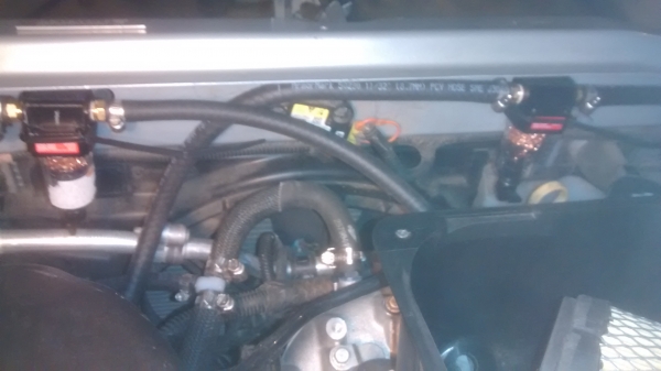
You can see the whitish plastic tee I installed in the booster hose low in the photo and left of center.
The can on the passenger side is to the turbo. GM plumbed the system with the minimum hose length. I've now got about 7' of hose on this can, I hope vacuum is not reduced too badly. Not sure how I could test it.
I'm actually not quite done, I'm waiting on that aluminum nipple for the manifold, should be here Wednesday.
After searching though endless webpages for a mounting bracket that I liked and would work, I remembered what you said, Dan, keep it simple. I decided to just zip tie them to the location I had picked out, which is inside the radiator support, one on each side. There is a pair of slotted holes on each side. I put a grommet in each hole and a small piece of velcro tape(just the fuzzy side, to protect the paint) on top and front of the catch cans. The grommets were 3/8" groove diameter and 1/16" groove uhhh.. I think it was called groove width, to fit the thickness of the sheetmetal. Fed the zip tie through one grommet, through the slotted holes, and through the other grommet. Then installed the grommets with needlenose pliers, pulling them down. simple.
Here they are all mounted and plumbed, view from driver seat.
You can see the whitish plastic tee I installed in the booster hose low in the photo and left of center.
The can on the passenger side is to the turbo. GM plumbed the system with the minimum hose length. I've now got about 7' of hose on this can, I hope vacuum is not reduced too badly. Not sure how I could test it.
I'm actually not quite done, I'm waiting on that aluminum nipple for the manifold, should be here Wednesday.
Moderator
Joined: 05-01-2014
Posts: 8,499
From: California
I finally found some copper scrub pads, at Kmart. Everywhere I went or called only had steel or copper coated. I unrolled a pad and cut off a small piece, folded it then wrapped it around the sintered brass filter. Then carefully screwed the bowl on, working the scrub pad into the bowl with a tiny screwdriver, so as not to mess up the O-ring at the top of the bowl.
I didn't plumb backwards. The vapor/air will enter the bowl, hit the scrub pad, with the contaminants dripping down into the bottom of the bowl(hopefully). Then the air will be drawn through the sintered brass filter and out. I hope this works.
I didn't plumb backwards. The vapor/air will enter the bowl, hit the scrub pad, with the contaminants dripping down into the bottom of the bowl(hopefully). Then the air will be drawn through the sintered brass filter and out. I hope this works.
Senior Member
Joined: 09-02-2010
Posts: 383
From: Philadelphia, PA
It could be that I misread this thread, but here's what I was thinking. Granted I'm also stock on my SS.
Like RJ mentioned Valve #1 of the valve cover in the center is fresh air in, which should already have a check valve to make sure dirty air can't flow.
Like you mentioned in #31 dwellscak, that clean air pressurizes the crankcase, then can either exit through Valve #2 (which will be connected to the catch can), or through the PCV in the intake manifold. If the PCV port is plugged, won't that force everything out of valve 2? If it does, that's why I would only have valve #2 connected to the IN of the catch can. Clean air 1 from the can then goes to the inlet of turbo, but I still need to get the clean air back into the intake manifold. That's where line 2 from the can comes into play - clean air 2 from the can to the PCV in an external housing to still have the functionality, then t'ed into the brake booster line so it gets back into the intake manifold. This should also keep all vacuum functionality, I believe.
If that doesn't work, then I can see why you would have to drill to get those vapors out of the manifold. That would mean Valve #2 and the drilled portion of the manifold both need to be T'ed into the input of the catch can. Clean air 1 to the turbo inlet, and clean air 2 to the intake manifold through the brake booster line.
Thread Starter
Senior Member
Joined: 05-29-2015
Posts: 542
From: Cleveland, OH
That being the case, I still see no need for a clean air return to the manifold. You've blocked it off. I mentioned port 2 ventilates the cam area, it will inadvertently ventilate the crankcase. But not nearly as well as Port 1/intake pcv. Which is tied directly to the intake through the crankcase.
I don't know what it will do if you try and draw everything from Port 2, I can assume it's not going to be as effective. Essentially the gases which used to enter the intake will now have to turn around and work there way back into the upper galleys. All while pressure is increasing, looking for an exit...
By Ting the two halves (let's call it upper and lower pcv) together in the input of your can. That makes sense, unfortunately I can't tell you how it's going to act. You're trying what Catman was thinking, bring the whole system together, filter it, send it back. I don't know the outcome, that's why I'm experimenting with cheap parts. More importantly, that's why I'm leaving the 2 systems separate. Trying to remain close to stock. Stock....lol
Moderator
Joined: 05-01-2014
Posts: 8,499
From: California
Stock disappeared from your rearview mirror many dollars ago. lol
I would have thought crankcase was crankcase, but I don't have an engine taken apart to study. To take it even further, I would have guessed that port #2 would be no worse, maybe even better(less restrictive?) than at the PCV valve location, because the poor vacuum force at the turbo would need all the help it can get.
He also has to tie into the manifold(booster hose) because that is the only good vacuum source at closed to partly open throttle.
If I've got something wrong, please say so.
Wow 100 posts on this thread already!!