
Installing an Oil Catch Can


Senior Member
Joined: 09-07-2008
Posts: 1,016
From: Mebane, NC
The yellowish area in between the upper (magenta) and lower (Cyan) dividers is actually a solid 2" od tube, and the coalescing material will go in there. I changed the opacity of tube so the inside feed tube could be seen.

Thread Starter
Senior Member
Joined: 05-29-2015
Posts: 542
From: Cleveland, OH
-that is indeed a 45* degree fitting into my intake manifold.
Hey thanks for the pic RJ, my light bulb moment there must have been in a daze waiting on planes all day! I wasn't even thinking, obviously! So I will be leaving port 1 in tact because we are still drawing a vacuum through our new fitting (why I didn't catch this, I'll chock up to lack of sleep)
I'm not sure if the ZZP intake tube protrudes inward as it does on the stocker, I'll have to look. So a mini-ram air coupled with negative crankcase pressure is going to draw in fresh air through port 1. Got it! Thanks again RJ!
Nice looking design there doc. The one you have completed, is it out for testing on your truck? I'm going with square tubing only so I have a surface to engrave in. Mine will probably also be a bit heavier.
Senior Member
Joined: 09-07-2008
Posts: 1,016
From: Mebane, NC
Not yet, hopefully this weekend. Been very busy at home cutting down trees and at work. Will report back my findings.

Moderator
Joined: 05-01-2014
Posts: 8,499
From: California
It occurred to me that I had not shown how I mounted the new, larger catch can on my fender. To just ziptie in the same location as the small can would not work, as the bottom of the larger can would contact the frame rail and therefore hang out of plumb. It would also be very close to the alternator pulley.
I took a Simpson 16 gauge RPS18 strap and drilled a 13/16" hole near each end. There's already a pilot hole on the right. The other hole was 8 3/4" on center.

Here are both holes drilled.

Then I cut off the excess material and filed any burrs or rough edges off.

The plan is to cut slots at the top of the holes I drilled, and drop the barb fittings of the catch can into these slots. So I needed a 5/16" slot for each hole. The legs are bent at 26*, this is to move the can forward in the engine bay so that the can does not contact the alternator pulley.
You can see the 5/16" slots, and you also see how I've bent one leg to the 26*. It's about 2 1/2" from the center of hole to the bend. I've bent the other leg only to 90* at this point, so that I can still get to the screw that will fasten the hanger to the fender. This bend is about 3 1/2" from the center of hole and about 3" to 3 1/4" between legs. After installing the hanger, I will complete the bend to 26*. The 2 legs will then be parallel to one another.

Now I have to hold the hanger in the location I want it to be in, and mark it for the 2 screws that will fasten it to the fender. I used 1/2" self-drilling lath screws. I predrilled the hanger, then fastened it to the fender with one screw. Then I leveled across the legs of the hanger and marked the location of the second screw on the fender.
Then I predrilled a pilot hole in the fender for the second screw, installed the hanger, and bent the leg parallel to the first. The catch can should be a snug fit between the legs of the hanger. Gently spring the legs apart and fit the catch can in place, slipping the barb fittings in the slots. Then push the hex part of the fittings into the 13/16" holes. Here it is installed, before I hooked up the lines.
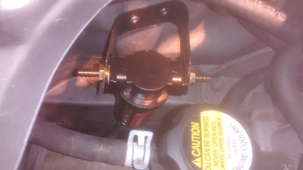
Looking down at it, the fittings are nice and parallel with the frame rail. The fittings are still at the same elevation as the small can was before, so gravity will still be helping the vapors get to the can.
I know what you're thinking, "Did he calculate the dimensions and angles in his head?" No, I'm not quite that good. I held the catch can in the location I desired, then made a prototype hanger out of lighter gauge metal.
For anyone that is planning to use the home depot air compressor filter as a catch can like I did, these dimensions should be pretty good for you. For those using a different can, but want the same location, the basic design, the concept here, should help you to figure out how to hang your catch can.
I took a Simpson 16 gauge RPS18 strap and drilled a 13/16" hole near each end. There's already a pilot hole on the right. The other hole was 8 3/4" on center.
Here are both holes drilled.
Then I cut off the excess material and filed any burrs or rough edges off.
The plan is to cut slots at the top of the holes I drilled, and drop the barb fittings of the catch can into these slots. So I needed a 5/16" slot for each hole. The legs are bent at 26*, this is to move the can forward in the engine bay so that the can does not contact the alternator pulley.
You can see the 5/16" slots, and you also see how I've bent one leg to the 26*. It's about 2 1/2" from the center of hole to the bend. I've bent the other leg only to 90* at this point, so that I can still get to the screw that will fasten the hanger to the fender. This bend is about 3 1/2" from the center of hole and about 3" to 3 1/4" between legs. After installing the hanger, I will complete the bend to 26*. The 2 legs will then be parallel to one another.
Now I have to hold the hanger in the location I want it to be in, and mark it for the 2 screws that will fasten it to the fender. I used 1/2" self-drilling lath screws. I predrilled the hanger, then fastened it to the fender with one screw. Then I leveled across the legs of the hanger and marked the location of the second screw on the fender.
Then I predrilled a pilot hole in the fender for the second screw, installed the hanger, and bent the leg parallel to the first. The catch can should be a snug fit between the legs of the hanger. Gently spring the legs apart and fit the catch can in place, slipping the barb fittings in the slots. Then push the hex part of the fittings into the 13/16" holes. Here it is installed, before I hooked up the lines.
Looking down at it, the fittings are nice and parallel with the frame rail. The fittings are still at the same elevation as the small can was before, so gravity will still be helping the vapors get to the can.
I know what you're thinking, "Did he calculate the dimensions and angles in his head?" No, I'm not quite that good. I held the catch can in the location I desired, then made a prototype hanger out of lighter gauge metal.
For anyone that is planning to use the home depot air compressor filter as a catch can like I did, these dimensions should be pretty good for you. For those using a different can, but want the same location, the basic design, the concept here, should help you to figure out how to hang your catch can.
Moderator
Joined: 05-01-2014
Posts: 8,499
From: California
This is the turbo-side can. The manifold-side can is mounted (ziptied) to the radiator support, in the same location as the small can was. Post #96, using the ziptie in the first pic, the can on the left of the second pic. Except now it's a bigger can and hooked up to a tank. 
Senior Member
Joined: 04-26-2009
Posts: 669
From: City of Champions
The 2.3 turbo EcoBoost folks are still coming out with new product & ideas that may help us...
NEW!!!! UPR PRODUCTS CLEAN SIDE CATCH CAN - 2015+ S550 Mustang Forum (GT, GT350, GT500, Mach 1, Ecoboost) - Mustang6G.com
http://www.uprproducts.com/mustang-b...coboost.html#1
NEW!!!! UPR PRODUCTS CLEAN SIDE CATCH CAN - 2015+ S550 Mustang Forum (GT, GT350, GT500, Mach 1, Ecoboost) - Mustang6G.com
http://www.uprproducts.com/mustang-b...coboost.html#1
Moderator
Joined: 05-01-2014
Posts: 8,499
From: California
The 2.3 turbo EcoBoost folks are still coming out with new product & ideas that may help us...
NEW!!!! UPR PRODUCTS CLEAN SIDE CATCH CAN - 2015+ S550 Mustang Forum (GT, GT350, GT500, Mach 1, Ecoboost) - Mustang6G.com
15-16 Mustang 2.3 Ecoboost Dual Valve Oil Catch Can Separator
NEW!!!! UPR PRODUCTS CLEAN SIDE CATCH CAN - 2015+ S550 Mustang Forum (GT, GT350, GT500, Mach 1, Ecoboost) - Mustang6G.com
15-16 Mustang 2.3 Ecoboost Dual Valve Oil Catch Can Separator

I don't understand the "clean side" catch can. It doesn't seem to have a vacuum source. Is this fresh air into the crankcase, then? If so, there shouldn't be anything to catch. Unless there's no check valve, and they're trying to catch what blows back into the intake tube. $230 instead of a simple check valve? What am I missing here?
Maybe they need it, but we don't?

Senior Member
Joined: 08-03-2010
Posts: 3,564
From: Lake Ronkonkoma, N.Y.