
Installing an Oil Catch Can


Thread Starter
Senior Member
Joined: 05-29-2015
Posts: 542
From: Cleveland, OH
I have to pull the camshaft because I want the upgraded e85 fuel lobe. While it's out the valves will seat enough so I can shell blast them. Or I might change over to the gen 2 cylinder head I've been porting! I probably won't do that though. If I pull the head I'll be tempted to replace the pistons/rods with forged units...with only 4000 miles I probably can't sell that to the wife as "necessary maintenance"
Busy working on my pcv mods at work today (shhhh) I should have some pics up later today
Busy working on my pcv mods at work today (shhhh) I should have some pics up later today

Platinum Member
Joined: 12-06-2009
Posts: 11,718
From: Alabama
But it already has forged rods. Just need to replace the cast pistons with forged units.
That is unless you're going totally full race crazy , and need some even better rods to go with those pistons.
That is unless you're going totally full race crazy

Senior Member
Joined: 09-07-2008
Posts: 1,016
From: Mebane, NC
I understand the e85 cam lobe.... but before you try and really pound on it make sure you have a means of logging it especially the HP rail pressure. I've seen split results with what you're doing. Still may not have enough displacement from the HP Pump to feed it. My feeling is that the fifth injector can be sized to feed it as long as you don't run out of intank fuel pump volume, and if you do it's much easier and cheaper to upgrade that pump to feed the injector. Logging is critical or you can end up with stuff going where it shouldn't be... pieces of piston in the oil pan... crushed/busted ring lands... you get the picture, although it isn't a pretty picture.
While they are forged rods, they still aren't strong enough to withstand a major pounding without doing the cool shape thing.
While they are forged rods, they still aren't strong enough to withstand a major pounding without doing the cool shape thing.
Thread Starter
Senior Member
Joined: 05-29-2015
Posts: 542
From: Cleveland, OH
The intake cam is more of a future investment. It will sit on my shelf with the Opel Fuel Injectors I picked up on Black Friday. Once I tune all of the existing kinks out of the system I can begin adding in my new headaches. And see where that gets us.
I'm finished the tapping and drilling portion of the PCV mod. Now I've got to come up with 2 catch cans and places to mount them. Shouldn't be difficult, all the parts can be sourced locally.
First up was the intake, since there's plenty of room on top of the intake, I chose to come out as close to the plug as possible. Also, I'll have room to bolt the intake on with new fitting installed, whew!


Next up was the valve cover. My fresh air IN port (CENTER) was blocked to allow room for the wastegate to clear. ZZP's instructions aren't clear why you're plugging this hole or what its used for. I also removed the straight tube on the passenger side so all my new hoses/fittings will match up.

I really didn't want to drill a hole in the wife's new turbo. Nevertheless, it had to be done. The Bullseye S256 does not have a fresh air line like our stock KO4 turbo. I needed to get a fitting as close to the impeller without impeding any airflow. I was able to notch a small section out of the housing on the bridgeport mill at work. The end result came out better than I had hoped. As you can see the fitting rest right on the ledge before the machined housing.


So that's it for now, I'll get working on some catch cans!
I'm finished the tapping and drilling portion of the PCV mod. Now I've got to come up with 2 catch cans and places to mount them. Shouldn't be difficult, all the parts can be sourced locally.
First up was the intake, since there's plenty of room on top of the intake, I chose to come out as close to the plug as possible. Also, I'll have room to bolt the intake on with new fitting installed, whew!
Next up was the valve cover. My fresh air IN port (CENTER) was blocked to allow room for the wastegate to clear. ZZP's instructions aren't clear why you're plugging this hole or what its used for. I also removed the straight tube on the passenger side so all my new hoses/fittings will match up.
I really didn't want to drill a hole in the wife's new turbo. Nevertheless, it had to be done. The Bullseye S256 does not have a fresh air line like our stock KO4 turbo. I needed to get a fitting as close to the impeller without impeding any airflow. I was able to notch a small section out of the housing on the bridgeport mill at work. The end result came out better than I had hoped. As you can see the fitting rest right on the ledge before the machined housing.
So that's it for now, I'll get working on some catch cans!
Thread Starter
Senior Member
Joined: 05-29-2015
Posts: 542
From: Cleveland, OH
All the fittings/lines are -4 JIC. It plays nicely with 1/8npt and the line gives me about the same ID. The cans are going to be 1/8npt. I also found a 1/2" fitting that will house our pcv valve quite nicely. I'll get some pics of it in line. If we can make it work for you I'll send ya one. Really excited to start catching oil. Just a few more mods and I can start putting it all back together. For the 4th time!
Senior Member
Joined: 09-07-2008
Posts: 1,016
From: Mebane, NC
All the fittings/lines are -4 JIC. It plays nicely with 1/8npt and the line gives me about the same ID. The cans are going to be 1/8npt. I also found a 1/2" fitting that will house our pcv valve quite nicely. I'll get some pics of it in line. If we can make it work for you I'll send ya one. Really excited to start catching oil. Just a few more mods and I can start putting it all back together. For the 4th time!
Got a bunch to do so I can get all the parts over to the coating people. When I get them back I'll post up pictures, may be awhile, really busy at work and have to go out of town for most of January. Orlando then, Oklahoma.... not looking forward to Oklahoma in Jan or Feb.
Kind of off topic but since you are a hydraulic and controls person also, we are doing a water hydraulics project for an Olympic training facility. The hydraulic fluid is pure tap water and we will be controlling a gate that determines how intense the water rapids are. Readers Digest condensed explanation... Gate has 3 individual 5" bore SS cylinders and I'll be using 3 electric servos to control 3 bi-directional pumps to control synchronizing, velocity, positioning and direction of the gate. Very environmentally safe, they have a leak and its only water so they aren't slicking the river. This technology is very new here in the US and we are the only distributor/integrator in the US for the product we are using. If your interested I will send pictures when we have it up and running.
Thread Starter
Senior Member
Joined: 05-29-2015
Posts: 542
From: Cleveland, OH
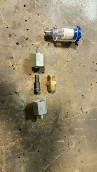
Here's the setup I've come up with to house the orginal PCV valve in-line with my new catch cans. There is only 1 shown but I intend on putting 2 on the intake side, 1 on the Valve cover. With the excess PCV pressure coming out of the compressor housing I do not want to "bottleneck" anything. I figure using two cans in parallel would be more than enough flow. I also definitely recommend using the correct GM PCV valves. The one on the turbo side is 100% shutoff, where as the the intake PCV valve will allow a slight amount of air the other direction. My guess is if it shut completely you could build enough intake pressure to possibly damage it.
The PCV valve fits snugly inside of the 1/2" NPT nipple. It's then surrounded by the two JIC fittings. Which will lead into the parallel cans and clean fresh air will be supplied through a new T on the brake booster line. If it causes turbulence braking, I'll make a new hole for it. But I don't see how putting it back there could cause an issue.
And compared to the previous can I installed.. this one is about 100% cheaper. Bought 3 cans @ $4.99 ea! Gotta love harbor freight. I'll also be running these backwards to keep oil in the bottom and fresh air coming out the top.

Moderator
Joined: 05-01-2014
Posts: 8,499
From: California
Great thread, very interesting! I have a few questions/theories. My engine is bone stock, unaltered GM.
Line #1, connecting to port #1 in your original post, is fresh air in. It has a check valve, air cannot flow back to the inlet, which is just downstream from the MAF sensor. If air cannot flow, there should be no oil vapor, and no need for a catch can in line #1.
Line #2, connecting port #2 to the mouth of the turbo, definitely needs a catch can. There is no check valve in that line. To me that means that, potentially, air could flow in either direction depending on either boost or vacuum condition. If you put a PCV valve in this line, won't that defeat the bidirectional function of this line? But with Line #1 as fresh air in, I wouldn't think Line #2 would need to flow back to the crankcase.
Line #3, for me is all internal. It sounds like you're rerouting that to be external, so that you can catch the oil vapor.
How snug is the PCV valve in the nipple? Could the pressurized air dislodge it, or even just leak around it?
Also, I think it was John Powell who said that you don't want to make line #2 too large, or you'll lose the little vacuum that you can gain from the turbo venturi effect. Are you running 2 lines there, would that defeat the vacuum? Am I not understanding where your parallel cans are going? Or is it that with your bigger turbo, you're getting a lot more vacuum than the K04?
Not trying to be a pain, just trying to help, and better understand.
Thanks, Randy
Thread Starter
Senior Member
Joined: 05-29-2015
Posts: 542
From: Cleveland, OH
Thanks RJ! I was never exactly sure which went where because I had already ditched the stock setup. Regardless, I'm not going to go back and correct the original post. We've learned so much since then.
I dug up a shot of the original PCV system. You are correct RJ.
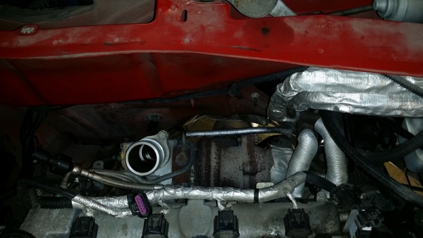
Not easy to see but the line with the PCV valve does run to the Center Port (#1) on the Valve Cover. The line from the turbo compressor goes to the Passenger Port (#2) on the Valve Cover. So again, correct RJ. We won't need a catch can on line 1. Because the valve keeps all that dirty air in the galleys.
We will need a can to keep dirty air from entering the turbo compressor housing (#2) The purpose of this line is too keep a constant vacuum in the upper galleys above the cams inside the valve cover. (sidenote: these baffles are plastic, I'm hoping they're high temp because I intend on powder coating this time around)
Line 3 is internal for everyone. As far as I can tell I haven't seen this mod done before. Mine could be the first! If it's not, someone has done there homework. Actually, according to ZZP I may have the ONLY GEN3/256 HHR! This will be where 90% of the oil will end up. I have a plan, not complete yet but I took a mock up shot for ya. Hopefully it helps.
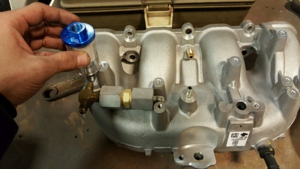
My intentions are pretty close to this. Dirty air comes from fitting I installed where the intake is now blocked off. It will enter the (now external) pcv through my "housing". From the PCV it will go into a T where I'll build parallel catch cans. Do I need 2? I have no idea () but I do know its going to catch A LOT of vapor. Making them parallel is key to not allow one to outflow the other. For 5 bucks and a few more fittings it's peace of mind! Like Doc said, they are ran backwards from there intended flow direction. This is to keep the oil at the bottom and fresh air coming out the top. From the parallels its just a matter of putting the clean air back into the intake. For simplicity I'm going to T in to the brake booster line.
I've had no luck from Mr. Powell. He did give me the insight to go the extra mile. I tried ordering his setup for months... If I had a question on this or that, it wouldn't be answered or just ignored. His kit does nothing with the intake PCV, which I why I had a pool of oil in the original GEN2 setup. I still haven't removed the intake from the GEN3, with 4000 miles I can't wait to see what ZZP has done to my valves/intake? I don't blame them, they haven't got it figured out yet obviously. What worries me is people with this setup who haven't done anything to correct the obvious issues it's causing (here's looking at you MississippiSunbrust, we'll get ya straight)
Randy, you can't offend by asking! The more we all learn the better! You wont find many detailed pics like the ones I've provided. I guess people want to keep all this info for themselves and sell it to others. I'd rather put it all out there and come up with the best solution by letting everyone work together. I hope your head isn't spinning...mine has finally slowed because there is light at the end of the tunnel. Just wish it wasn't 15* outside!!
I dug up a shot of the original PCV system. You are correct RJ.
Not easy to see but the line with the PCV valve does run to the Center Port (#1) on the Valve Cover. The line from the turbo compressor goes to the Passenger Port (#2) on the Valve Cover. So again, correct RJ. We won't need a catch can on line 1. Because the valve keeps all that dirty air in the galleys.
We will need a can to keep dirty air from entering the turbo compressor housing (#2) The purpose of this line is too keep a constant vacuum in the upper galleys above the cams inside the valve cover. (sidenote: these baffles are plastic, I'm hoping they're high temp because I intend on powder coating this time around)
Line 3 is internal for everyone. As far as I can tell I haven't seen this mod done before. Mine could be the first! If it's not, someone has done there homework. Actually, according to ZZP I may have the ONLY GEN3/256 HHR! This will be where 90% of the oil will end up. I have a plan, not complete yet but I took a mock up shot for ya. Hopefully it helps.
My intentions are pretty close to this. Dirty air comes from fitting I installed where the intake is now blocked off. It will enter the (now external) pcv through my "housing". From the PCV it will go into a T where I'll build parallel catch cans. Do I need 2? I have no idea (
I've had no luck from Mr. Powell. He did give me the insight to go the extra mile. I tried ordering his setup for months... If I had a question on this or that, it wouldn't be answered or just ignored. His kit does nothing with the intake PCV, which I why I had a pool of oil in the original GEN2 setup. I still haven't removed the intake from the GEN3, with 4000 miles I can't wait to see what ZZP has done to my valves/intake? I don't blame them, they haven't got it figured out yet obviously. What worries me is people with this setup who haven't done anything to correct the obvious issues it's causing (here's looking at you MississippiSunbrust, we'll get ya straight)
Randy, you can't offend by asking! The more we all learn the better! You wont find many detailed pics like the ones I've provided. I guess people want to keep all this info for themselves and sell it to others. I'd rather put it all out there and come up with the best solution by letting everyone work together. I hope your head isn't spinning...mine has finally slowed because there is light at the end of the tunnel. Just wish it wasn't 15* outside!!