When you click on links to various merchants on this site and make a purchase, this can result in this site earning a commission. Affiliate programs and affiliations include, but are not limited to, the eBay Partner Network.
Radio Battery Constant 12v+ Wire: Red/White
Radio Ground Wire: Black/White
Stereo Power Antenna Trigger Wire: Pink
Stereo Amp Turn-On Trigger Wire: Pink
Left Front Speaker Positive Wire (+): Tan
Left Front Speaker Negative Wire (-): Dark Green
Right Front Speaker Positive Wire (+): Light Green/White
Right Front Speaker Negative Wire (-): Light Green
Left Rear Speaker Positive Wire (+): Brown
Left Rear Speaker Negative Wire (-): Brown/White
Right Rear Speaker Positive Wire (+): Dark Blue
Right Rear Speaker Negative Wire (-): Tan
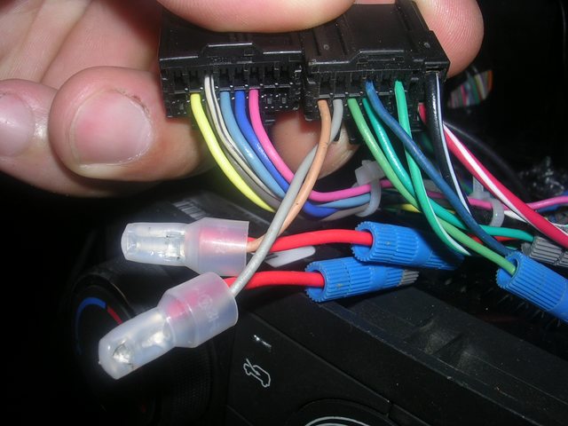
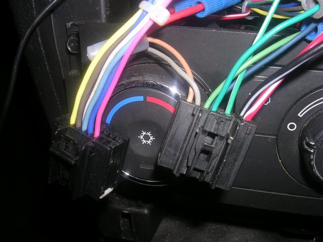
I know this is an old post, however I am attempting to upgrade my stereo and have found myself with the EXACT setup as the images above. It seems that only a select few vehicles have these different colored wires and I have found zero information on the color codes for them. As you can see in the image above, there is an orange wire, a light blue wire, a yellow wire, all that do not match with any of the 2011 Chevy HHR stereo color wire diagrams.
How do you check if the controls are working.
11 dark blue14 white blackI was told to put a voltmeter between 11 and 14 and press the control on the steering wheel if the voltage change is seen then the controls are working. So number 11 should have 10 volts to start? Put the volt meter on 11 and a ground and should get 10 volts is this right? Then probe both wires and press the buttons and the voltage should change. If this is true what happens if there is no change?
No. #11 is the signal from the SWC. When a button is pushed there should be a voltage on it. The voltage would be different depending on which button is pressed.
The whit/bk wire is 10 V ref, dark blue is the signal. The buttons are attached to resistors.
You do notice those are 2 connectors in the diagram?
Yes I made a mistake in my post. So the white black should always have 10 volts to it correct?
And the dark blue one should get voltage when I push a button. Different voltage for different buttons.?
I will check again in the morning there seems to be something that's not right. Thank you
No. #11 is the signal from the SWC. When a button is pushed there should be a voltage on it. The voltage would be different depending on which button is pressed.
The whit/bk wire is 10 V ref, dark blue is the signal. The buttons are attached to resistors.
You do notice those are 2 connectors in the diagram?
So number 14 pin says 10 volt ref. What does the ref stand for?
The 14 pin is it supplying 10 volts to something? Or receiving 10 volts? If so from where?
And the number 11 pin the dark blue wire that is coming from the SWC.
I'm trying to figure this all out to get the swc to work. The unit I have that connects to those two wires is not getting the signal. So I am trying to troubleshoot where the issue is.
So if the 11 pin is supplying voltage. What is the color wire going up into the steering column that supplies the power to that switch? I'm trying to avoid taking the steering wheel apart. There is no voltage coming out of that 11 pin wire. Or where would the fuse be for that specific switch? I checked all the fuses under the hood and in the console to the right passenger side everything is okay.
ref means that it is exactly 10 volts because it is a digital circuit.
The radio supplies 10 v ref to the SWC. The buttons are connected from the 10v ref to a resistor that sends a voltage to the radio. Something like (made up values): tune up=8v, tune down=7v,vol up=6v,vol down = 5v.
The SWC gets the 10v ref on the blk/wht on pin 14 ON THE RADIO.
The colors on the diagram continue to the steering wheel.
I don't know how your adapter is wired, talk to the manufacturer. My guess is that it gets accessory voltage and makes it 10v ref because the radio doesn't have that pin.
As far as I can see you just connect 2 wires from the module to 2 wires on the switch an the 12v and ground to the car, the plug the phono jack into the other adapter.
Crutchfield.com provides FREE help and wiring diagrams.
Here is the instructions for a PAC SWI-ADAPT module from the crutchfield site, I guess most others are similar.