


Kenwood DPX500BT Owners


Thread Starter
New Member
Joined: 10-18-2014
Posts: 22
From: California
oldracer,
Thanks for the reply. In the directions for the aftermarket wire harness (LC-GMRC-LAN-03) it says to connect the Orange/White wire to the illumination wire of the aftermarket Radio. I did this and discovered that it had no effect on the illumination of the unit. Upon closer examination I discovered that the pin of the Orange/White wire of this aftermarket connector is attached to pin # 2 of the 14 pin vehicle connector. Which should have a gray wire going off into the vehicle. As stated earlier, there is no wire , gray or otherwise, in #2 of this connector in my vehicle.
Thanks for the reply. In the directions for the aftermarket wire harness (LC-GMRC-LAN-03) it says to connect the Orange/White wire to the illumination wire of the aftermarket Radio. I did this and discovered that it had no effect on the illumination of the unit. Upon closer examination I discovered that the pin of the Orange/White wire of this aftermarket connector is attached to pin # 2 of the 14 pin vehicle connector. Which should have a gray wire going off into the vehicle. As stated earlier, there is no wire , gray or otherwise, in #2 of this connector in my vehicle.
Thread Starter
New Member
Joined: 10-18-2014
Posts: 22
From: California
Here is the pin out of the connector in my vehicle. See link for pin locations.
1. Red/White
2. empty (supposed to be GRAY?)
3. empty
4. Dark Green
5. Light Green
6. Gray (LF Speaker out (-)
7. Tan
8. Black/White
9. Green/White
10. empty
11. Dark Blue
12. empty
13. empty
14. empty
https://www.chevyhhr.net/gallery/fil...diagram-p1.jpg
1. Red/White
2. empty (supposed to be GRAY?)
3. empty
4. Dark Green
5. Light Green
6. Gray (LF Speaker out (-)
7. Tan
8. Black/White
9. Green/White
10. empty
11. Dark Blue
12. empty
13. empty
14. empty
https://www.chevyhhr.net/gallery/fil...diagram-p1.jpg

Platinum Member
Joined: 12-06-2009
Posts: 11,721
From: Alabama
Here is the pin out of the connector in my vehicle. See link for pin locations.
1. Red/White
2. empty (supposed to be GRAY?)
3. empty
4. Dark Green
5. Light Green
6. Gray (LF Speaker out (-)
7. Tan
8. Black/White
9. Green/White
10. empty
11. Dark Blue
12. empty
13. empty
14. empty
https://www.chevyhhr.net/gallery/fil...diagram-p1.jpg
1. Red/White
2. empty (supposed to be GRAY?)
3. empty
4. Dark Green
5. Light Green
6. Gray (LF Speaker out (-)
7. Tan
8. Black/White
9. Green/White
10. empty
11. Dark Blue
12. empty
13. empty
14. empty
https://www.chevyhhr.net/gallery/fil...diagram-p1.jpg
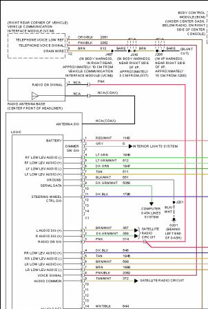
And #2 gray wire going to the interior lights system.
Wiring schematics are not always dead on accurate. Some changes can occur during a cars production run.
Just not sure why you don't have that gray wire. There has to be a feed from the dimming system or interior lighting that is on that circuit. I mean, how else could the HU display dim if it was not tied to that circuit ?
Just a thought. Since there are 2 connectors, did you check the other connector for that missing "gray" wire ? The schematic shows that wire in connector 1, but who knows for sure.
Moderator
Joined: 01-23-2009
Posts: 26,536
From: Fredericksburg,VA
BTW, that seems to be digital signal wire, from the BCM that controls that sort of thing.
I suggest applying a hi/lo signal to the pin (#2). That is typically +5 0r less than +5, but may vary. A DVOM would be handy, especially since the ohm/continuity function applies a voltage.
I suggest applying a hi/lo signal to the pin (#2). That is typically +5 0r less than +5, but may vary. A DVOM would be handy, especially since the ohm/continuity function applies a voltage.
Platinum Member
Joined: 12-06-2009
Posts: 11,721
From: Alabama
Just to clarify, this is where I got my info. May not be the same as what donbrew gave you( sorry I cut off the bottom, nothing important there)
I did notice mine shows #14 being white/blk , not gray like donbrew noted.
I did notice mine shows #14 being white/blk , not gray like donbrew noted.
Platinum Member
Joined: 12-06-2009
Posts: 11,721
From: Alabama

Honestly, I'm not computer savy but I'll try to explain how I did it. I'll PM you later.(after I confirm with my wife, the one with the college degree in computerology.
 )
)
Thread Starter
New Member
Joined: 10-18-2014
Posts: 22
From: California
firemangeorge,
Thanks for the reply. One thing I did notice that was different from the diagram that donbrew provided is that on the one you provided, the gray wire on #2 does not terminate at the logic unit. All of the other wires continue on through X1 and are connected to the logic unit. #2 stops at X1 and says Dimmer SW Sig between there and the logic unit.
I sent Kenwood Tech Support a message and asked them what signal should be applied on the dimmer control wire connected to the radio. Not sure if I'll get an answer from them, but I figured it was worth a try.
Thanks for the reply. One thing I did notice that was different from the diagram that donbrew provided is that on the one you provided, the gray wire on #2 does not terminate at the logic unit. All of the other wires continue on through X1 and are connected to the logic unit. #2 stops at X1 and says Dimmer SW Sig between there and the logic unit.
I sent Kenwood Tech Support a message and asked them what signal should be applied on the dimmer control wire connected to the radio. Not sure if I'll get an answer from them, but I figured it was worth a try.


Thread
Thread Starter
Forum
Replies
Last Post

