
Installing an Oil Catch Can


Senior Member
Joined: 08-03-2010
Posts: 3,564
From: Lake Ronkonkoma, N.Y.
Don't the 2 locations of the turbo line and PCV both have the same crankcase pressure? Why can't both be teed together into one can and forget about the one line venting to the turbo inlet altogether?

Moderator
Joined: 05-01-2014
Posts: 8,499
From: California
Cat Man, right now, in this science experiment, we're still testing theories. You've seen me go back and forth on whether I feel 1 or 2 cans may be better. I think Dan and Dennis are going with 2 separate systems, at least initially.
I am running with 2 separate systems as well, initially. I plan to go for 1000 or maybe 2000 miles and measure how much fluid I catch. Then I plan to tee the 2 vacuum sources into one can, with 1 vapor draw point, and go an equal distance. After that, I plan to keep the vacuum sources teed, but change to the other vapor draw point.
If one of these 3 designs is clearly better, then I'll use that design. But results still may not be conclusive. The test of the first design may be all local driving, and the second may be a trip halfway across the country. I hope to have an answer by the end of summer, but it may not come until December.
How many miles are on your SS? Are you planning to clean the valves and relocate the PCV valve soon?

Senior Member
Joined: 09-07-2008
Posts: 1,016
From: Mebane, NC
Here are some picture of how the air is moving in and out of the crankcase.


WHere I have it marked as BOV that should read Bypass Valve


Need to understand how the oil vapor/mist is moving in and around around the crankcase, hopefully you can see my feeble attempt of trying to explain it.
There are two distinct places the oil vapor/mist is being drawn into the inlet system, one is the inlet of the turbo, the other is the intake manifold through the PCV valve. I don't want to interrupt what has been designed into the motor that is why I'm choosing to use two cans.
Hopefully this helps.
WHere I have it marked as BOV that should read Bypass Valve
Need to understand how the oil vapor/mist is moving in and around around the crankcase, hopefully you can see my feeble attempt of trying to explain it.
There are two distinct places the oil vapor/mist is being drawn into the inlet system, one is the inlet of the turbo, the other is the intake manifold through the PCV valve. I don't want to interrupt what has been designed into the motor that is why I'm choosing to use two cans.
Hopefully this helps.
Last edited by DrLoch; Mar 3, 2016 at 07:22 AM. Reason: Add comment below picture 3.

Thread Starter
Senior Member
Joined: 05-29-2015
Posts: 542
From: Cleveland, OH
Thanks Doc! That should help the others who don't have a torn down engine to look through. You snuck in while I was composing...had to edit in
A science experiment to say the least! I'm really happy that it's working period. No matter the number of cans/vacuum sources, the point is to remove dirty crankcase air. This is why I'm ditching the port 1 pcv and using 3 cans. It may end up being 2 with 1 having a completely separate chamber for port 1 -> intake tube.
RJ, since you've got the equipment and you're running. Is it possible for you to gauge the line from the intake tube to the factory external pcv? Port 1 is fresh air into the crankcase. I'm curious how often that line is actually providing fresh air. Seeing as it's just upstream from the turbo's port 2 fitting I have reason to believe it's not ever positive pressure.
Light bulb moment...with our manifold mod there's probably no fresh air coming through the port 1 pcv.
What I think is the port 1 pcv is used to draw fresh air in while the intake manifold is in vacuum. Which it is, unless your stomping on it. There's no way for the intake tube itself to provide fresh air, rather it's drawn out by the intake manifold on the opposite side of the crankcase. As I've said before, as long as it's running the intake tubing is always under vacuum.
Trouble is, now we've plugged the main path for fresh air to be drawn into the crankcase. That's why I'm ditching everything from the factory and plumbing everything to its own can. Right or wrong, the air will be clean returning to the engine.
- thoughts everyone?
You know what's awesome, this thread hasn't turned into a complete shamble like A LOT of similar threads. It's literally chocked full of good info and hard evidence. Just omit the first 4 pages where I was learning and figuring out what not buy!
If anyone is interested I'll probably have enough material to make a few more cans. Mine will be powder coated and then I'm going to engrave the SS script into the front and let the aluminum show through. Will look very professional! Just need to get it off paper and put it together.
Moderator
Joined: 05-01-2014
Posts: 8,499
From: California
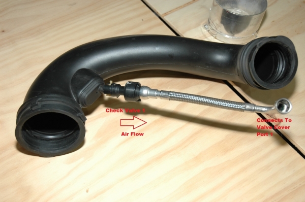
This is what the fresh air sees right after it passes by the MAF sensor. It's a hole roughly 1/4" in diameter. Then the air goes through the check valve and into port #1.

I think this is like a mini "ram-air" effect, coupled with any negative pressure in the crankcase from a vacuum source. The air is probably only entering here part time. If there is very little blow-by, very little crankcase pressure, then the vacuum(manifold) will draw air in as needed to evacuate pressure.
When boosting, lots of blow-by, lots of crankcase pressure, very little vacuum help from the turbo, it will be very difficult(not to mention unnecessary and even counterproductive) to draw air into the crankcase from here.
If you put a can in this line, you won't catch but maybe the tiniest amount of water vapor from the incoming air. There will be no airflow in the other direction with the check valve in place, so no catching there, either. Now if you remove the check valve, you may catch vapors on their way out. Of course, that is straying from GM's design. And in stock configuration, this is a line that is sending zero muck to the intake system.
When boosting, the higher pressure in the crankcase will help move the vapors to that weak vacuum source that is the turbo. If you remove the check valve, that's like opening another faucet, airspeed will decrease to the catch cans, and the vapor will be more likely to fall out of suspension.
The vapors in the "fresh air" line that didn't quite make it to the can, when you let off the throttle, will start traveling back to the crankcase with the incoming air(there's that Tug-O-War again) unless you put a check valve in(thanks again, donbrew), going the opposite direction from stock. But then you have no fresh air in.
We still are applying manifold vacuum at our new manifold port. At idle, I measured 19" at the brake booster hose, and 19" at our new manifold port.
I don't know what the result will be. One more design, one more set of testing, I guess. But I wouldn't do it.
Last edited by RJ_RS_SS_350; Mar 17, 2016 at 03:24 PM.
Senior Member
Joined: 08-03-2010
Posts: 3,564
From: Lake Ronkonkoma, N.Y.
I have 31K miles. I would like to do the intake mod soon and clean the valves.
Can you show the external PCV fitting in the intake manifold?
Do you know how much crankcase pressure is there with and without boost?
Doc
Thanks for the pictures

Senior Member
Joined: 09-07-2008
Posts: 1,016
From: Mebane, NC
Here is what I'm doing, already built one ordering more cans now.


These are jpegs of my conceptual drawings so some of the minor detail lacking.
These are jpegs of my conceptual drawings so some of the minor detail lacking.
Last edited by DrLoch; Mar 3, 2016 at 08:45 AM. Reason: Added more verbage
Moderator
Joined: 05-01-2014
Posts: 8,499
From: California
Here is the fitting that Dbelscak put on his(from post #44). It's about an inch from the manifold-to-head bolting flange. Mine is in the same location, which is under the stock airbox. I had thought that DB had drilled at that angle, but now I'm thinking that is a 45* fitting.

I think to accurately measure crankcase pressure at idle, I would need to pinch the hose on port #2 and measure at the intake manifold fitting, while plugging the vacuum leak at the catch can. It wouldn't be too difficult.
But to measure at boost, I'd have to do all that and rig my gauge on the windshield, similar to how I did to measure vacuum. The problem is I'd have to drive it with no crankcase ventilation, which is not good at all. I think that would be a test to do at a shop, on a dyno, where you only have to run like that for a few seconds.
And the data from the idle test would be about worthless without the data from the boost test.