Cranks and dies P1682 & P0689
 02-14-2024, 08:38 AM
#11
Senior Member

Join Date: 03-29-2022
Location: Davison MI
Posts: 1,035
Fix this first.
DIAGNOSTIC FAULT INFORMATION
IMPORTANT: Always perform the Diagnostic System Check - Vehicle prior to using this diagnostic procedure. Testing and Inspection

TYPICAL SCAN TOOL DATA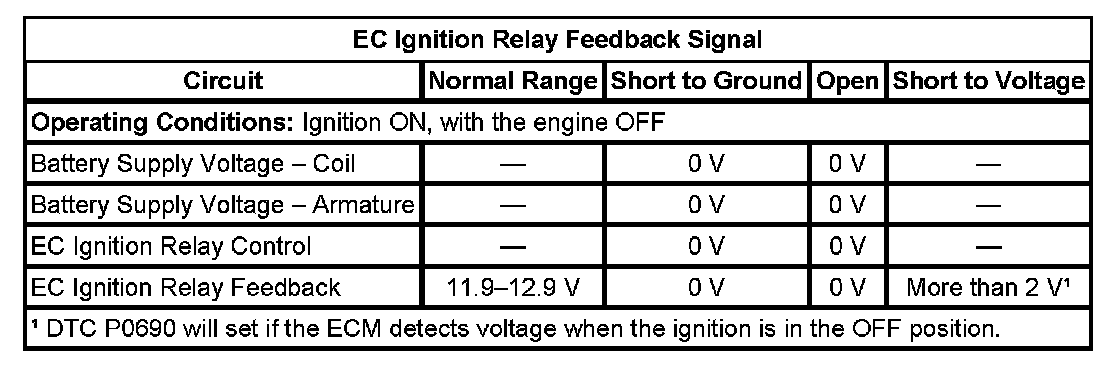
CIRCUIT/SYSTEM DESCRIPTION
The powertrain relay is a normally open relay. The relay switch is held in the open position by spring tension. Battery positive voltage is supplied directly to the relay coil and the relay switch contact at all times. The engine control module (ECM) supplies the ground path to the relay coil control circuit through an output driver module (ODM). The ODM for the powertrain relay also incorporates a fault detection circuit, which is continuously monitored by the ECM. When the ECM commands the powertrain relay ON, ignition 1 voltage is supplied to fuses in the underhood fuse block.
The ignition 1 voltage that is supplied to the ECM, provides power to the internal ECM circuits associated with the throttle actuator control (TAC) operation. The ECM also monitors the voltage level on the ignition 1 voltage circuit to confirm that the powertrain relay contacts have closed.
CONDITIONS FOR RUNNING THE DTC
P0685 and P0689
- The battery voltage is between 9-18 volts.
- The ignition is ON.
- The powertrain relay has been commanded ON.
P0690
- The battery voltage is between 9-16 volts.
- The ignition is OFF.
- The powertrain relay has been commanded OFF.
CONDITIONS FOR SETTING THE DTC
P0685
- The commanded state of the ODM does not match and the actual state of the control circuit.
- The condition is present for more than 5 seconds.
P0689
- The ECM detects less than 10 volts on the ignition 1 voltage circuit from to the ECM.
- The condition is present for more than 5 seconds.
P0690
- The ECM detects more than 2 volts on the ignition 1 voltage circuit to the ECM.
- The condition is present for more than 2 seconds.
ACTION TAKEN WHEN THE DTC SETS
- The control module stores the DTC information into memory when the diagnostic runs and fails.
- The malfunction indicator lamp (MIL) will illuminate.
- The control module records the operating conditions at the time the diagnostic fails. The control module stores this information in failure records.
- The driver information center (DIC), if equipped, may display a message.
CONDITIONS FOR CLEARING THE DTC
- A current DTC, last test failed clears when the diagnostic runs and passes.
- A history DTC clears after 40 consecutive warm up cycles, if this or any other related diagnostic reports no other failures.
- Clear the DTC with a scan tool.
DIAGNOSTIC AIDS
- This test procedure assumes that the vehicle battery has passed a load test and is completely charged. Refer to Battery Inspection/Test. Battery Inspection/Test
- When disconnecting electrical connectors or removing fuses and relays from a fuse block, always inspect the component electrical terminals for corrosion and the mating electrical terminals for correct tension.
CIRCUIT/SYSTEM VERIFICATION
1. With the ignition ON, engine OFF, command the powertrain relay ON and OFF several times using the scan tool output control function. You should either hear or feel the relay click with each command.
2. With the ignition ON, engine OFF, probe both test points of each of the fuses supplied with voltage by the powertrain relay.
- The test lamp should illuminate on at least one test point of each fuse. If the test lamp does not illuminate continue with Circuit/System Testing.
CIRCUIT/SYSTEM TESTING
1. With the ignition OFF, remove the powertrain relay from the underhood fuse block.
2. With the ignition ON, measure for battery positive voltage, B+, between the relay coil voltage supply circuit and ground.
- If the voltage measures less than B+, repair the open or high resistance in the circuit to the relay coil. All wire circuit resistance should measure less than 2 ohms.
3. Measure for voltage between the relay coil control circuit and ground.
- If voltage is measured on the control circuit of the relay, test for a short to voltage.
4. Connect a test lamp between the battery positive voltage supply circuit of the relay coil and the relay coil control circuit. Use a scan tool to command the powertrain relay ON and OFF. The test lamp should turn ON and OFF when toggling between the commanded states.
- If the test lamp stays ON all the time, test for a short to ground on the relay coil control circuit or a faulty ECM.
- If the test lamp stays OFF all the time, test for an open or high resistance on the relay coil control circuit or a faulty ECM. All wire circuit resistance should measure less than 2 ohms.
5. Measure for B+ between the relay armature supply circuit, and ground.
- If the voltage measures less than B+, repair the open or high resistance in the circuit to the relay armature. All wire circuit resistance should measure less than 2 ohms.
6. With the ignition ON, test for voltage on each test point of the ETC fuse.
- If voltage is present, test the ignition 1 voltage circuit between the ECM, the powertrain relay, and the ETC fuse for a short to voltage.
- If both circuits test normal, replace the ECM.
7. Connect a 20-amp fused jumper wire between the B+ terminal and the ignition 1 voltage terminal of the powertrain relay at the underhood fuse block. With a test lamp, probe both test points of the ETC fuse.
- If the test lamp illuminates at both test points of the ETC fuse, repair the ignition 1 voltage circuit between the powertrain relay and the ECM for an open, high resistance, or a faulty ECM. All wire circuit resistance should measure less than 2 ohms.
- If the test lamp only illuminates at one test point of the ETC fuse, repair the short to ground in the ignition 1 voltage circuit between the fuse and the applicable component. Replace the fuse, as necessary.
- If the test lamp does not illuminate on either test point of the ETC fuse, repair the open or high resistance between the powertrain relay and the ETC fuse. All wire circuit resistance should measure 2 ohms or less.
8. With a test lamp, test for voltage on both test points of the following fuses:
- ETC Fuse
- Emission 1 Fuse
- If the test lamp fails to illuminate on one test point of each fuse, repair the open or high resistance between the fuse and the powertrain relay. All wire circuit resistance should measure 2 ohms or less.
COMPONENT TESTING
- Measure for 70-110 ohms between terminals 85 and 86 of the relay.
- If the resistance is not within the specified range, replace the relay.
- Measure for infinite resistance between terminals 30 and 86 of the relay.
- If continuity is detected, replace the relay.
- Measure for infinite resistance between terminals 30 and 87 of the relay.
- If continuity is detected, replace the relay.
- Measure for infinite resistance between terminals 30 and 85 of the relay.
- If continuity is detected, replace the relay.
- Measure for infinite resistance between terminals 85 and 87 of the relay.
- If continuity is detected, replace the relay.
- Connect a 20-amp fused jumper wire from the battery positive cable at the battery, to relay terminal 85. Connect a jumper wire from the negative battery cable at the battery, to relay terminal 86. Measure for less than 2 ohms between terminals 30 and 87 of the relay, with a DMM.
- If the resistance measures more than 2 ohms, replace the relay.
REPAIR INSTRUCTIONS
1. Refer to Engine Control Module (ECM) Replacement for ECM replacement, setup, and programming.
2. Clear the DTCs with a scan tool.
3. Turn OFF the ignition for 30 seconds.
4. Start the engine. If engine does not run, refer to Engine Cranks but Does Not Run. Engine Cranks But Does Not Run
5. If other DTCs are set, refer to Diagnostic System Check - Vehicle. Testing and Inspection
pro multis � About Operation CHARM
P0689
DIAGNOSTIC FAULT INFORMATION
IMPORTANT: Always perform the Diagnostic System Check - Vehicle prior to using this diagnostic procedure. Testing and Inspection
TYPICAL SCAN TOOL DATA
EC Ignition Relay Feedback Signal:
CIRCUIT/SYSTEM DESCRIPTION
The powertrain relay is a normally open relay. The relay switch is held in the open position by spring tension. Battery positive voltage is supplied directly to the relay coil and the relay switch contact at all times. The engine control module (ECM) supplies the ground path to the relay coil control circuit through an output driver module (ODM). The ODM for the powertrain relay also incorporates a fault detection circuit, which is continuously monitored by the ECM. When the ECM commands the powertrain relay ON, ignition 1 voltage is supplied to fuses in the underhood fuse block.
The ignition 1 voltage that is supplied to the ECM, provides power to the internal ECM circuits associated with the throttle actuator control (TAC) operation. The ECM also monitors the voltage level on the ignition 1 voltage circuit to confirm that the powertrain relay contacts have closed.
CONDITIONS FOR RUNNING THE DTC
P0685 and P0689
- The battery voltage is between 9-18 volts.
- The ignition is ON.
- The powertrain relay has been commanded ON.
P0690
- The battery voltage is between 9-16 volts.
- The ignition is OFF.
- The powertrain relay has been commanded OFF.
CONDITIONS FOR SETTING THE DTC
P0685
- The commanded state of the ODM does not match and the actual state of the control circuit.
- The condition is present for more than 5 seconds.
P0689
- The ECM detects less than 10 volts on the ignition 1 voltage circuit from to the ECM.
- The condition is present for more than 5 seconds.
P0690
- The ECM detects more than 2 volts on the ignition 1 voltage circuit to the ECM.
- The condition is present for more than 2 seconds.
ACTION TAKEN WHEN THE DTC SETS
- The control module stores the DTC information into memory when the diagnostic runs and fails.
- The malfunction indicator lamp (MIL) will illuminate.
- The control module records the operating conditions at the time the diagnostic fails. The control module stores this information in failure records.
- The driver information center (DIC), if equipped, may display a message.
CONDITIONS FOR CLEARING THE DTC
- A current DTC, last test failed clears when the diagnostic runs and passes.
- A history DTC clears after 40 consecutive warm up cycles, if this or any other related diagnostic reports no other failures.
- Clear the DTC with a scan tool.
DIAGNOSTIC AIDS
- This test procedure assumes that the vehicle battery has passed a load test and is completely charged. Refer to Battery Inspection/Test. Battery Inspection/Test
- When disconnecting electrical connectors or removing fuses and relays from a fuse block, always inspect the component electrical terminals for corrosion and the mating electrical terminals for correct tension.
CIRCUIT/SYSTEM VERIFICATION
1. With the ignition ON, engine OFF, command the powertrain relay ON and OFF several times using the scan tool output control function. You should either hear or feel the relay click with each command.
2. With the ignition ON, engine OFF, probe both test points of each of the fuses supplied with voltage by the powertrain relay.
- The test lamp should illuminate on at least one test point of each fuse. If the test lamp does not illuminate continue with Circuit/System Testing.
CIRCUIT/SYSTEM TESTING
1. With the ignition OFF, remove the powertrain relay from the underhood fuse block.
2. With the ignition ON, measure for battery positive voltage, B+, between the relay coil voltage supply circuit and ground.
- If the voltage measures less than B+, repair the open or high resistance in the circuit to the relay coil. All wire circuit resistance should measure less than 2 ohms.
3. Measure for voltage between the relay coil control circuit and ground.
- If voltage is measured on the control circuit of the relay, test for a short to voltage.
4. Connect a test lamp between the battery positive voltage supply circuit of the relay coil and the relay coil control circuit. Use a scan tool to command the powertrain relay ON and OFF. The test lamp should turn ON and OFF when toggling between the commanded states.
- If the test lamp stays ON all the time, test for a short to ground on the relay coil control circuit or a faulty ECM.
- If the test lamp stays OFF all the time, test for an open or high resistance on the relay coil control circuit or a faulty ECM. All wire circuit resistance should measure less than 2 ohms.
5. Measure for B+ between the relay armature supply circuit, and ground.
- If the voltage measures less than B+, repair the open or high resistance in the circuit to the relay armature. All wire circuit resistance should measure less than 2 ohms.
6. With the ignition ON, test for voltage on each test point of the ETC fuse.
- If voltage is present, test the ignition 1 voltage circuit between the ECM, the powertrain relay, and the ETC fuse for a short to voltage.
- If both circuits test normal, replace the ECM.
7. Connect a 20-amp fused jumper wire between the B+ terminal and the ignition 1 voltage terminal of the powertrain relay at the underhood fuse block. With a test lamp, probe both test points of the ETC fuse.
- If the test lamp illuminates at both test points of the ETC fuse, repair the ignition 1 voltage circuit between the powertrain relay and the ECM for an open, high resistance, or a faulty ECM. All wire circuit resistance should measure less than 2 ohms.
- If the test lamp only illuminates at one test point of the ETC fuse, repair the short to ground in the ignition 1 voltage circuit between the fuse and the applicable component. Replace the fuse, as necessary.
- If the test lamp does not illuminate on either test point of the ETC fuse, repair the open or high resistance between the powertrain relay and the ETC fuse. All wire circuit resistance should measure 2 ohms or less.
8. With a test lamp, test for voltage on both test points of the following fuses:
- ETC Fuse
- Emission 1 Fuse
- If the test lamp fails to illuminate on one test point of each fuse, repair the open or high resistance between the fuse and the powertrain relay. All wire circuit resistance should measure 2 ohms or less.
COMPONENT TESTING
- Measure for 70-110 ohms between terminals 85 and 86 of the relay.
- If the resistance is not within the specified range, replace the relay.
- Measure for infinite resistance between terminals 30 and 86 of the relay.
- If continuity is detected, replace the relay.
- Measure for infinite resistance between terminals 30 and 87 of the relay.
- If continuity is detected, replace the relay.
- Measure for infinite resistance between terminals 30 and 85 of the relay.
- If continuity is detected, replace the relay.
- Measure for infinite resistance between terminals 85 and 87 of the relay.
- If continuity is detected, replace the relay.
- Connect a 20-amp fused jumper wire from the battery positive cable at the battery, to relay terminal 85. Connect a jumper wire from the negative battery cable at the battery, to relay terminal 86. Measure for less than 2 ohms between terminals 30 and 87 of the relay, with a DMM.
- If the resistance measures more than 2 ohms, replace the relay.
REPAIR INSTRUCTIONS
1. Refer to Engine Control Module (ECM) Replacement for ECM replacement, setup, and programming.
2. Clear the DTCs with a scan tool.
3. Turn OFF the ignition for 30 seconds.
4. Start the engine. If engine does not run, refer to Engine Cranks but Does Not Run. Engine Cranks But Does Not Run
5. If other DTCs are set, refer to Diagnostic System Check - Vehicle. Testing and Inspection
pro multis � About Operation CHARM


Thread
Thread Starter
Forum
Replies
Last Post