
Explanation on how the charging system works


Thread Starter
Platinum Member
Joined: 04-09-2006
Posts: 7,043
From: Vancouver, BC, Canada
Explanation on how the charging system works
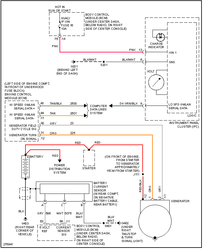
The charging goes to the BCM then to the ECM (computer) to regulate the charging system as needed. The ECM is what controls/regulates all charging. the sensor you changed tells the BCM ( body computer) what the battery level is. The BCM then takes that info, sends to ECM and the ECM then adjusts voltage. Losing output 100% leads to a most likely failed ECM as it cant control/regulate charging. This is only true with good alternator and battery and cable connections. here is the formal description.
Charging System Description and Operation
Electrical Power Management (EPM) Overview
The electrical power management (EPM) system is designed to monitor and control the charging system and send diagnostic messages to alert the driver of possible problems with the battery and generator. This EPM system primarily utilizes existing on-board computer capability to maximize the effectiveness of the generator, to manage the load, improve battery state-of-charge (SOC) and life, and minimize the system's impact on fuel economy. The EPM system performs 3 functions:
�It monitors the battery voltage and estimates the battery condition.
�It takes corrective actions by adjusting the regulated voltage.
�It performs diagnostics and driver notification.
The battery's condition is estimated during key-off and during key-on. During key-off the SOC of the battery is determined by measuring the open-circuit voltage. The SOC is a function of the acid concentration and the internal resistance of the battery, and is estimated by reading the battery open circuit voltage when the battery has been at rest for several hours.
The SOC can be used as a diagnostic tool to tell the customer or the dealer the condition of the battery. Throughout key-on, the algorithm continuously estimates SOC based on adjusted net amp hours, battery capacity, initial SOC, and temperature.
While running, the battery's degree of discharge is primarily determined by a battery current sensor, which is integrated to obtain net amp hours.
In addition, the EPM function is designed to perform regulated voltage control (RVC) to improve battery SOC, battery life, and fuel economy. This is accomplished by using knowledge of the battery's SOC and temperature to set the charging voltage to an optimum battery voltage level for recharging without detriment to battery life.
The Charging System Description and Operation is divided into 3 sections. The first section describes the charging system components and their integration into the EPM. The second section describes charging system operation. The third section describes the instrument panel cluster (IPC) operation of the charge indicator, driver information center (DIC) messages, and voltmeter operation.
Charging System Components
Generator
The generator is a serviceable component. If there is a diagnosed failure of the generator it must be replaced as an assembly. The engine drive belt drives the generator. When the rotor is spun it induces an alternating current (AC) into the stator windings. The AC voltage is then sent through a series of diodes for rectification. The rectified voltage has been converted into a direct current (DC) for use by the vehicles electrical system to maintain electrical loads and the battery charge. The voltage regulator integral to the generator controls the output of the generator. It is not serviceable. The voltage regulator controls the amount of current provided to the rotor. If the generator has field control circuit failure, the generator defaults to an output voltage of 13.8 volts.
Body Control Module (BCM)
The body control module (BCM) is a GM LAN device. It communicates with the engine control module (ECM) and the instrument panel cluster (IPC) for electrical power management (EPM) operation. The BCM determines the output of the generator and sends the information to the ECM for control of the generator field control circuit. It monitors the generator field duty cycle signal circuit information sent from the ECM for control of the generator. It monitors a battery current sensor, the battery positive voltage circuit, and estimated battery temperature to determine battery state-of-charge (SOC). The BCM performs idle boost and load management operations.
Battery Current Sensor
The battery current sensor is a serviceable component that is connected to the negative battery cable at the battery. The battery current sensor is a 3-wire hall effect current sensor. The battery current sensor monitors the battery current. It directly inputs to the BCM. It creates a 5-volt pulse width modulation (PWM) signal of 128 Hz with a duty cycle of 0-100 percent. Normal duty cycle is between 5-95 percent. Between 0-5 percent and 95-100 percent are for diagnostic purposes.
Engine Control Module (ECM)
The ECM directly controls the generator field control circuit input to the generator. It monitors the generators generator field duty cycle signal circuit and sends the information to the BCM. The ECM will override the BCM control of the generator when one of the following conditions are met:
�The engine cooling fans are on high speed.
�There is a high fuel demand.
�The calculated ambient air temperature is less that 0�C (32�F).
Instrument Panel Cluster (IPC)
The IPC provides a means of customer notification in case of a failure and a voltmeter. There are 2 means of notification, a charge indicator and a driver information center (DIC) message of SERVICE CHARGING SYSTEM and CHARGING SYSTEM FAULT.
Charging System Operation
The purpose of the charging system is to maintain the battery charge and vehicle loads. There are 6 modes of operation and they include:
�Charge Mode
�Fuel Economy Mode
�Voltage Reduction Mode
�Start-up Mode
�Windshield Deice Mode
�Battery Sulfation Mode
The engine control module (ECM) controls the generator through the generator L-terminal control circuit. The signal is a 5-volt pulse width modulation (PWM) signal of 128 Hz with a duty cycle of 0-100 percent. Normal duty cycle is between 5-95 percent. Between 0-5 percent and 95-100 percent are for diagnostic purposes.


Senior Member
Joined: 06-07-2011
Posts: 2,180
From: SE Mich
Thanks for your efforts. This is a keeper.
One bone to pick, though. Under Charging System Components, that should read Alternator (generates AC), rather than Generator (generates DC). I'm only trying to help put this into a sticky...
One bone to pick, though. Under Charging System Components, that should read Alternator (generates AC), rather than Generator (generates DC). I'm only trying to help put this into a sticky...


Moderator
Joined: 01-23-2009
Posts: 26,539
From: Fredericksburg,VA
Thread Starter
Platinum Member
Joined: 04-09-2006
Posts: 7,043
From: Vancouver, BC, Canada
Right! Still mystifies me as to why - to me it's an alternator. Doing a search on amazon or ebay for an HHR generator won't likely result in much if anything.
All that said in the first post still hasn't helped me figure out the electrical gremlins in my 2006 though. LOL
ps: I didn't write it but found it semi-helpful. Hopefully others will get something out of it.
All that said in the first post still hasn't helped me figure out the electrical gremlins in my 2006 though. LOL
ps: I didn't write it but found it semi-helpful. Hopefully others will get something out of it.

Thread
Thread Starter
Forum
Replies
Last Post
kmcrae476
Problems/Service/Repairs
5
May 25, 2015 11:19 PM