
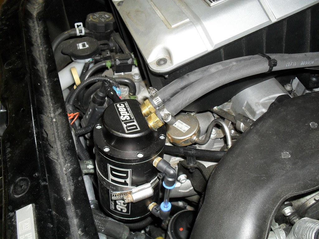
Installing an Oil Catch Can


Moderator
Joined: 05-01-2014
Posts: 8,509
From: California
I could replace the drain valve with one of the 1/4" male NPT to barb fittings left over from the small cans. Plumb that with a hose into a tank, and put the drain valve on the bottom of the tank. I could increase capacity by a lot.
I get lots of ideas. They're not all good ones, but sometimes...
Moderator
Joined: 05-01-2014
Posts: 8,509
From: California
I went ahead and built the muck collection tanks, and then tested vacuum. I plugged my vacuum gauge into the tee at the brake booster hose. At idle, it read 19 inches of vacuum. Then tested at the end of the line, where it plugs into the manifold, and still got 19 inches. 
I then moved on to the turbo-side line, plugging it right into the turbo port. I routed the line up and trapped the gauge with the windshield wiper. Went for a drive, and while boosting, I could only get up to 4 inches of vacuum, very disappointing.
I've kinda been ignoring a CEL for misfire and low fuel rail pressure because i think it was a momentary fault, and the car has been running great. I know I was getting at least 10 PSI of boost during the test(kinda hard to watch both gauges and the road while boosting), so even at full 14-15 PSI, it's not gonna be much more than 4 inches.
Moderator
Joined: 05-01-2014
Posts: 8,509
From: California
The only good place I could find for the muck collection tanks is behind the bumper cover, one on either side of the radiator. I decided, why not just build them out of PVC pipe and caps?
I should warn you that mounting the tanks was not easy. Squeezing my impact driver into the engine bay, with the hoses, wires, radiator and fan was very challenging. My older, larger DeWalt impact would not fit, but I had a smaller Ridgid that barely made it.
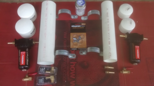
After removing the bumper cover, I could see that I could only fit 2" pipe on the driver side, and 2 1/2" pipe on the passenger side. Here is a material list
1' of 2" PVC pipe
1' of 2 1/2" PVC Pipe
(2) 2" caps
(2) 2 1/2" caps
(4) 1/4" male NPT X 5/16" or 3/8" hose elbows
(2) 1/4" male NPT x 5/16" or 3/8" hose straight
4' of hose (I had some 11/32 pcv hose left over)
(1) 2" 2-hole strap (electrical department)
(1) 2 1/2" 2-hole strap
1/2" self drilling lath screws
(2) 1/4" NPT air shut-off valves (removed from catch cans)
(6) hose clamps
PVC cement
It would probably be a little easier to use 2" pipe and caps on both sides. The pic shows 2 of each pipe strap. I tried to use them as a pair of 1-hole straps on each pipe, but the mount was not secure. Now don't cheap out and get fittings and hose that is smaller. Remember, this is muck, it may not flow real well, it may clog a smaller hose.
These tanks ended up being about 8 1/2" long, you could make them a little shorter, but I wouldn't go any longer. You don't want to be more than about 1/2" above the frame rail, or you won't get the bumper cover back on.
Drill and tap the end caps and build your tanks. Remove the air shut-off valve from the catch cans, and install the elbows loosely for now. You'll fine tune where they point later. Install elbows in the tops of the tanks, and put the shut-offs in the bottom loosely so you can position the valve handle later. Install the 1/4" male NPT x straight hose fittings in the shut-offs.
I spray painted the tanks, but honestly, you can't see them once everything is put back together.
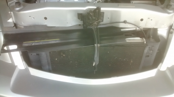
Remove the 2 short rods that the bumper cover screwed to, one on either side of the radiator, and the vertical piece of plastic that the rods poke through. Remove the 2 brackets that hold the top of the radiator in place, and the horizontal plastic piece from the top of the radiator.
Place the 2-hole strap just under the cap, so that the strap will support the tank. You may have to tweak the strap a little, the legs are a little short to reach the frame rail. The 2 1/2" straps are a lot short, but the 3" is too big. This is why I said 2" pipe on both sides would be easier.
Position the tank no more than 1/2" above the frame rail and as far back towards the radiator support as the 2-hole straps will allow. Mark the front hole, predrill, and carefully put a screw in through the 2-hole strap(with the tank in place). If you try to just run the screw in, it will shear right off. Slowly impact it into the hole, you may want to switch to a new screw, or 2, or 3. You may find it necessary to lift the radiator up out of it's mounting hole and push it back into the engine bay a bit to give your impact the clearance it needs. Seems you can only move one side of the radiator at a time. Repeat for the other tank.
Getting a screw in the back hole is very challenging. Forget about predrilling. You'll have to remove the coolant recovery tank to get the passenger side done. I removed the oil dipstick from it's tube, it helped with something, but I can't remember what it was. You'll have to push the radiator up out of the mounting hole again, pushing it forward this time. Do all this and it will still be very difficult, but possible. Get the right length extension and bit for your impact, you may have to put them in the impact after the impact is in place. Trial and error. Don't give up!
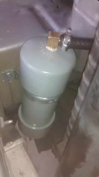
Here is the passenger side tank installed
Once the tanks are installed, you can measure carefully and mark where the hose will need to pass through vertical plastic pieces that you removed from either side of the radiator. Then drill the hole and fine tune, if necessary, with a half round file and utility knife. Here are both tanks showing the hoses installed.
Passenger side
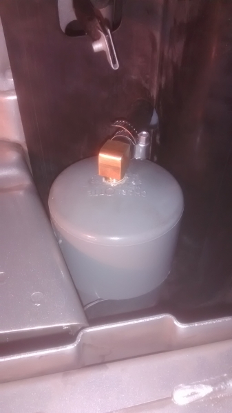
Driver side

And both sides installed. Notice the driver side tank has a straight pipe fitting on the top. I had to change that to an elbow(as I said above) for clearance for the bumper cover.

Now fine tune the elbows in the bottom of your catch cans, and the placement of the handles for the drain valves on the bottoms of the tanks. Put everything back together, the bumper cover, oil dipstick, everything.
Almost done! You just need to hole-saw directly below the drain valves, and attach a short piece of hose, so you can drain the tanks when the time comes.
My 2 1/2" inch tank holds 3 cups of fluid, and the 2" tank holds 2 cups. So with the hose between the tank and the catch can, and about an ounce in the catch can, I have about 26 oz and 18 oz capacity.. I'll put the car on ramps so I can reach the drain valves, place containers under the hoses, and drain away!!
I should warn you that mounting the tanks was not easy. Squeezing my impact driver into the engine bay, with the hoses, wires, radiator and fan was very challenging. My older, larger DeWalt impact would not fit, but I had a smaller Ridgid that barely made it.
After removing the bumper cover, I could see that I could only fit 2" pipe on the driver side, and 2 1/2" pipe on the passenger side. Here is a material list
1' of 2" PVC pipe
1' of 2 1/2" PVC Pipe
(2) 2" caps
(2) 2 1/2" caps
(4) 1/4" male NPT X 5/16" or 3/8" hose elbows
(2) 1/4" male NPT x 5/16" or 3/8" hose straight
4' of hose (I had some 11/32 pcv hose left over)
(1) 2" 2-hole strap (electrical department)
(1) 2 1/2" 2-hole strap
1/2" self drilling lath screws
(2) 1/4" NPT air shut-off valves (removed from catch cans)
(6) hose clamps
PVC cement
It would probably be a little easier to use 2" pipe and caps on both sides. The pic shows 2 of each pipe strap. I tried to use them as a pair of 1-hole straps on each pipe, but the mount was not secure. Now don't cheap out and get fittings and hose that is smaller. Remember, this is muck, it may not flow real well, it may clog a smaller hose.
These tanks ended up being about 8 1/2" long, you could make them a little shorter, but I wouldn't go any longer. You don't want to be more than about 1/2" above the frame rail, or you won't get the bumper cover back on.
Drill and tap the end caps and build your tanks. Remove the air shut-off valve from the catch cans, and install the elbows loosely for now. You'll fine tune where they point later. Install elbows in the tops of the tanks, and put the shut-offs in the bottom loosely so you can position the valve handle later. Install the 1/4" male NPT x straight hose fittings in the shut-offs.
I spray painted the tanks, but honestly, you can't see them once everything is put back together.
Remove the 2 short rods that the bumper cover screwed to, one on either side of the radiator, and the vertical piece of plastic that the rods poke through. Remove the 2 brackets that hold the top of the radiator in place, and the horizontal plastic piece from the top of the radiator.
Place the 2-hole strap just under the cap, so that the strap will support the tank. You may have to tweak the strap a little, the legs are a little short to reach the frame rail. The 2 1/2" straps are a lot short, but the 3" is too big. This is why I said 2" pipe on both sides would be easier.
Position the tank no more than 1/2" above the frame rail and as far back towards the radiator support as the 2-hole straps will allow. Mark the front hole, predrill, and carefully put a screw in through the 2-hole strap(with the tank in place). If you try to just run the screw in, it will shear right off. Slowly impact it into the hole, you may want to switch to a new screw, or 2, or 3. You may find it necessary to lift the radiator up out of it's mounting hole and push it back into the engine bay a bit to give your impact the clearance it needs. Seems you can only move one side of the radiator at a time. Repeat for the other tank.
Getting a screw in the back hole is very challenging. Forget about predrilling. You'll have to remove the coolant recovery tank to get the passenger side done. I removed the oil dipstick from it's tube, it helped with something, but I can't remember what it was. You'll have to push the radiator up out of the mounting hole again, pushing it forward this time. Do all this and it will still be very difficult, but possible. Get the right length extension and bit for your impact, you may have to put them in the impact after the impact is in place. Trial and error. Don't give up!
Here is the passenger side tank installed
Once the tanks are installed, you can measure carefully and mark where the hose will need to pass through vertical plastic pieces that you removed from either side of the radiator. Then drill the hole and fine tune, if necessary, with a half round file and utility knife. Here are both tanks showing the hoses installed.
Passenger side
Driver side
And both sides installed. Notice the driver side tank has a straight pipe fitting on the top. I had to change that to an elbow(as I said above) for clearance for the bumper cover.
Now fine tune the elbows in the bottom of your catch cans, and the placement of the handles for the drain valves on the bottoms of the tanks. Put everything back together, the bumper cover, oil dipstick, everything.
Almost done! You just need to hole-saw directly below the drain valves, and attach a short piece of hose, so you can drain the tanks when the time comes.
My 2 1/2" inch tank holds 3 cups of fluid, and the 2" tank holds 2 cups. So with the hose between the tank and the catch can, and about an ounce in the catch can, I have about 26 oz and 18 oz capacity.. I'll put the car on ramps so I can reach the drain valves, place containers under the hoses, and drain away!!

Senior Member
Joined: 08-03-2010
Posts: 3,564
From: Lake Ronkonkoma, N.Y.
Nice RJ
What's nice about plastic, oil is attracted to it. Have a water filtering system at work that separate's oil from water in the steam room where we wash parts. It uses large plastic tubing where it starts to recycle the water and collect the oil.
You could have used tubing clamps instead of the strap style. They only have one hole in them to make your install a little easier.

On to an update with the can I built for just the turbo.
Changed the oil yesterday and inspected the catch can that had 3,000 miles on it.
There was not a drop of oil in it!
Took the can apart and the bottom was bone dry. I squeezed the mess element and did have a "small" trace of oil.
Three things come to mine:
1) The mess element is to coarse to trap fumes. Should now use sintered bronze and should that be placed on the inlet or outlet fitting?
2) The down pipe has too many holes in it. I can use shrink tubing to cover up them up. The stuff I have has glue on the ID that will activate when heated to make a good bond.
3) Scrap this can for now and do the air compressor filter design.
What's nice about plastic, oil is attracted to it. Have a water filtering system at work that separate's oil from water in the steam room where we wash parts. It uses large plastic tubing where it starts to recycle the water and collect the oil.
You could have used tubing clamps instead of the strap style. They only have one hole in them to make your install a little easier.
On to an update with the can I built for just the turbo.
Changed the oil yesterday and inspected the catch can that had 3,000 miles on it.
There was not a drop of oil in it!
Took the can apart and the bottom was bone dry. I squeezed the mess element and did have a "small" trace of oil.
Three things come to mine:
1) The mess element is to coarse to trap fumes. Should now use sintered bronze and should that be placed on the inlet or outlet fitting?
2) The down pipe has too many holes in it. I can use shrink tubing to cover up them up. The stuff I have has glue on the ID that will activate when heated to make a good bond.
3) Scrap this can for now and do the air compressor filter design.
Moderator
Joined: 05-01-2014
Posts: 8,509
From: California
On to an update with the can I built for just the turbo.
Changed the oil yesterday and inspected the catch can that had 3,000 miles on it.
There was not a drop of oil in it!
Took the can apart and the bottom was bone dry. I squeezed the mess element and did have a "small" trace of oil.
Three things come to mine:
1) The mess element is to coarse to trap fumes. Should now use sintered bronze and should that be placed on the inlet or outlet fitting?
2) The down pipe has too many holes in it. I can use shrink tubing to cover up them up. The stuff I have has glue on the ID that will activate when heated to make a good bond.
3) Scrap this can for now and do the air compressor filter design.
4) Such a poor vacuum source(I only got 4 inches of vacuum) has a hard time pulling uphill. And remember, it's not an "instant on", it takes awhile to depressurize all that hose(and the can), and you may only be in boost for a few seconds at a time. The stock setup was 10" of hose running downhill. Now you're running 3' of hose uphill to the can and another 3' back to the turbo. I think that makes a big difference.
Your #1 and 2, if correct, mean that the vapors are getting past the media. But there would still be residue on the walls of the can, and in the hose going back to the vacuum source.
No, I think your catch can design looks good, but I would suggest you try mounting it low so gravity can work for you, not against you.
I just noticed how you put the compression fitting through the lid of your can. Is that a good seal? You're not losing vacuum there(or anywhere) are you?
I got about 1/2 oz from the turbo-side can in about 500 miles. But keep in mind I was driving hard, in rainy weather. If you don't drive hard in the rain, who knows if you'll catch anything. It doesn't rain much around here, I may not catch anymore in that can. And now I have a 3-cup tank to depressurize, too, so who knows, only time will tell if I catch anymore.
PS I agree, those clamps, in pairs, probably would work well for mounting the tank. I guess I was impatient, couldn't source them locally, didn't want to wait for delivery. I had hoped those straps would work in pairs with one screw in each strap, but no.
Senior Member
Joined: 08-03-2010
Posts: 3,564
From: Lake Ronkonkoma, N.Y.
RJ
I took a cotton swab and did both the inlet and outlet of the can. No real oil was present.
I just wiped my finger inside the can walls, no oil.
I feel the mounting of the can is fine:
The inlet runs close to parallel to the engine port and outlet runs down to the turbo port.
The compression fitting is tight, trust me.
As far as vacuum. Vacuum is vacuum. Take a shop vac, holding the hose above your head or at the floor you still have the same vacuum. You only start to have a vacuum differential when in a vacuum environment.
With both of your filters do you see more oil collected from the PCV vs the Turbo?
I took a cotton swab and did both the inlet and outlet of the can. No real oil was present.
I just wiped my finger inside the can walls, no oil.
I feel the mounting of the can is fine:

The inlet runs close to parallel to the engine port and outlet runs down to the turbo port.
The compression fitting is tight, trust me.
As far as vacuum. Vacuum is vacuum. Take a shop vac, holding the hose above your head or at the floor you still have the same vacuum. You only start to have a vacuum differential when in a vacuum environment.
With both of your filters do you see more oil collected from the PCV vs the Turbo?
Senior Member
Joined: 08-03-2010
Posts: 3,564
From: Lake Ronkonkoma, N.Y.
Just found this picture:
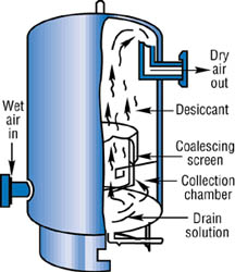
This is for an air compressor filter. It did worked for you RJ, so then,
I think I must put a bronze filter at the end of my down tube and close off the other holes I made. Given the low amount of oil vapors (and/or vacuum) to collect, instead of passing by the inefficient media I now have in the can. And forget about the desiccant that is used in this diagram.
I could also make my inlet at the base of the can as shown in the picture.
Moderator
Joined: 05-01-2014
Posts: 8,509
From: California
As far as vacuum. Vacuum is vacuum. Take a shop vac, holding the hose above your head or at the floor you still have the same vacuum. You only start to have a vacuum differential when in a vacuum environment.
With both of your filters do you see more oil collected from the PCV vs the Turbo?
With both of your filters do you see more oil collected from the PCV vs the Turbo?
Same weak shop vac, with 20' of hose, on for a few seconds at a time, trying to vacuum dirt out of a hole in the ground. It's not going to work nearly as well. Turn the vac off, the dirt goes back in the hole.
The fact that you had no residue backs that up. It means there was no oil to filter out. It rarely made it to the can. It looks like the top of your can is about 6" higher than port #2. It starts to move towards the can, but then you let off the throttle a little bit, the turbo slows down, you lose vacuum, and the oil runs back down to the valve cover. See if you've got residue at the other end(port #2).
That's my theory, anyway. You're relieving crankcase pressure, that's good. But you're not getting the muck out of the crankcase. If you had a can on the manifold side also, you could let that can do the job of getting the muck out. At 19 inches(at idle) of nearly constant vacuum, it can move the vapors uphill without much difficulty. Or maybe if you tee the clean side into manifold vacuum(with check valves), then the manifold vacuum could take over when the turbo loses vacuum, and could keep that vapor moving. But you would still have muck entering the intake through the PCV valve.
As for which of my cans caught more, I don't think i have a good answer yet. They both seemed to catch the same amount(and I bet a lot of it was water vapor from the rain), but they had very little wool in them, and some muck was getting by. Probably a lot more got by the manifold can due to stronger vacuum. So I would be guessing that the manifold can should see a lot more vapor.
These new cans I built should be a lot better at filtering, a lot more wool, and more densely packed. Plus with the tanks, the muck can immediately leave the catch can and the air has no chance of picking it up and trying to carry it to the intake or turbo.
Now, the tank on the turbo side may work against me. By the time the low vacuum can depressurize the tank, I may already be off the throttle. I wonder if a check valve inline between the can and the tank would keep the tank at negative pressure? Probably not. Just have to wait and see what happens, I guess.
Senior Member
Joined: 08-03-2010
Posts: 3,564
From: Lake Ronkonkoma, N.Y.
RJ
Your theory of the vacuum deals with a restriction. If the filter in the shop vac is dirty it will make suction harder. And yes dirt will get sucked in better with the hose up (gravity).
Being that the can for the turbo doesn't see a more constant vacuum like one connected to the PCV/manifold, I would think this can is not the real issue. Maybe to the point that it isn't needed?
So let's back up. Manifold high Hg/Turbo low Hg. But both must be sent to contain oil vapor so not to get to the intake valves.
With the system you have made you still don't think both can't be made into one recovery tank?
Moderator
Joined: 05-01-2014
Posts: 8,509
From: California
Shoot, I can't seem to make up my mind. Now I'm back to thinking a 2 can system might be better, and here's why.
In a 2 can system, any amount of suction could potentially draw vapors from the crankcase, both sources could potentially draw at the same time if there was a little bit of vacuum in the manifold and a lot of air was moving past the port at the turbo.
With 1 can, and a PCV or check valve in each line, I would think that when one source had stronger vacuum, it would cause the valve in the opposite line to close.
What do you guys think?
In fact, when the boost/vacuum gauge is at zero we're probably not drawing vapor at all, from either source. At that point, gravity would be the only force that could move oil towards the can. Well, there may be a little push from the crankcase pressure.
Wow, there's a lot more to this than just putting a filter in-line and driving on!