When you click on links to various merchants on this site and make a purchase, this can result in this site earning a commission. Affiliate programs and affiliations include, but are not limited to, the eBay Partner Network.
Now you need to drill and tap the intake manifold. 11/32" drill bit and 1/8" NPT tap is required. Also a 1/8" NPT fitting of your choice. I would just caution you to not just run the tap all the way in. Tap a little, test your fitting. Repeat until your fitting feels like it fits good and tight. If you just run the tap all the way, you may have a loose fitting "fitting"(a leak). You can always go back and remove more material, but you can't put it back if you go too far.
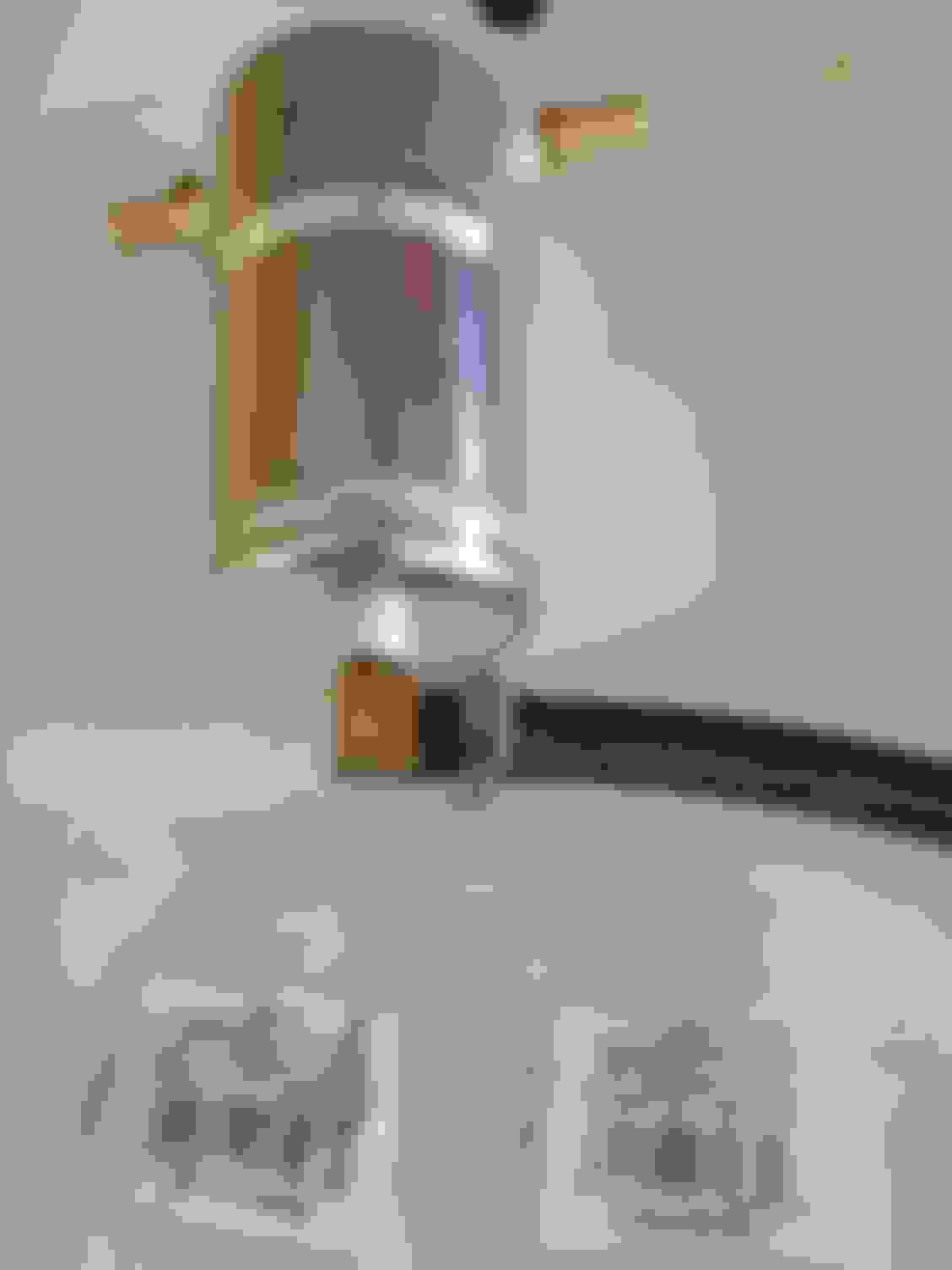
Here is the fitting installed on the intake. Yes, it was leaking. I had tried an aluminum radiator drain fitting, due to concerns over galvanic corrosion. I later changed it to a brass fitting, no more leaks.
The catch cans need to be installed inline.
One(intake-side), between the fitting you just installed, and the power brake booster vacuum line. Install the factory PCV valve between the can and the brake line. I ran a 1/2" hose from a barb fitting on the catch can, ground a little bit of the lip off the PCV valve (where the O-ring is now), and clamped the 1/2" hose directly to the PCV valve. Then a 5/16" hose clamped directly to the small end of the PCV valve to a barbed tee in the booster hose. Like this.
The second can(turbo-side), installs between port #2 in this pic, and the turbo. You can remove the existing steel braided line from the turbo, but the end on port #2 is easiest removed by destroying it. The line, not the port. No biggie, you won't need the line anymore.
After some trials, I built the catch cans that I currently am using.
Some fluid was getting through the filtration, So I started looking for ways to get the liquid to condense, and fall out of the air stream. I started with just copper tubing. Thanks to Cat Man HHR for suggesting coolers. Here is that part of the project, as well as where and how I mounted the intake-side catch can.
Continue reading through post #344 for both coolers. After that is mostly just data on how much muck I was catching with each drain.
Here is a drawing of the current configuration of my system. The red lines to the muck tanks aren't actually "dirty air", as labeled, but actually "dirty drip". I've put the factory PCV valve inline, between the catch can and the brake booster line.
Many thanks to Dbeluscak and DrLoch, as well as donbrew, oldblue, Cat Man HHR, and many others who have contributed to this project.
I've tried to gather all the necessary information, all here in one place. Let me know if anything seems to be missing. There's still a lot to read here, but it's much less than the nearly 40 pages in the catch can thread.
Last edited by RJ_RS_SS_350; Dec 15, 2017 at 09:01 PM.
Just passing this on for anybody else wanting to do this.
I right now only have a separator for the turbo and it doesn't really collect oil. I believe it's because of the K&N intake pipe, it has no check valve like the OEM.
Will install OEM pipe and R&I intake manifold after the winter to install fitting and second separator.
RJ,
How many miles were on the engine when you did this?
How bad were the valves coked up?
Was synthetic oil used at every oil change?
Thanks
Took a little digging, but I found some answers!
I discovered the problem at 86,000 miles. No driveability issues, no codes. But valves in #4 coked bad enough to cause low compression.
And from the shell blasting thread:
"22. I performed another leak down test here. My prior readings - cylinders 1-3 had 2-4% leakage, and cylinder 4 had 23% leakage(crankcase and intake). Now cylinders 1-3 have 2% leakage and cylinder 4 has 5-6% leakage (crankcase). These results are better than I expected. They are not as clean as the BMW machines get them, but they were pretty good."
And I have used Mobil1 on every oil change since I've owned it, May of 2014.
And I have used Mobil1 on every oil change since I've owned it, May of 2014.
Just using your car as a base line compared to mine.
Yours is a 2009 vs mine 2010.
You had 86K on it vs my 20K when bought.
Don't know the milage you blasted the valves.
Both of us use Mobil 1 when change is do.
I change mine before the DIC say's about 20%.
There were records that the original owner of mine did oil changes about every 3K when he had it. Don't know what oil used.
I know this isn't going to happen tomorrow, but when I R&I intake, I'm curious how much coking is on my valves. Will look at #4 as a possible cylinder for a larger amount.
I now have 45K and in the spring/summer maybe 2K more.
I first drilled and tapped the bottom of the bowl, for the fitting that drains to the collection tank.
I purchased a 1" PVC coupler at the hardware store. The inside of one end had to be sanded(quite a bit) so that it would fit tightly over the supplied filter holder. Once I got it sized and forced all the way on, then I grinded down part of the outside of the PVC coupler, so that the bowl would thread back on.
I needed 1" of pipe to extend from the coupler, to better achieve chambering of the catch can.
Then I packed the 1" pipe with the stainless pot scrubber pad material, packed more pot scrubber material around the 1"pipe, and carefully threaded on the bowl.
I was able to use the same mounting bracket as the previous can used, with only slight modification. I punched out the center knockout(remember, it is a modified 4" electrical junction box). Then I drilled out another hole to 1/4". I bought a 6mm cap screw and split washer at the hardware store. Replacing the unneeded dipstick, this screw went through the 1/4" hole(with pipe thread sealant) and became a mounting screw.
I used one of the supplied fittings through the knockout hole as another mounting screw, where they show the(unwanted) breather. More sealant and a cap. Replaced some lines for length, rerouted other lines, done.
Last edited by RJ_RS_SS_350; Nov 7, 2019 at 09:24 AM.