LED MOD - Radio, HVAC, I/P - Step-By-Step Tutorial 2006-2008
 03-01-2009, 12:43 PM
#1
Senior Member
Thread Starter

Join Date: 02-09-2009
Location: New Jersey
Posts: 296
Ever want to change your Factory Lights on the Instrument Panel, Radio, & others. Well now you can. I have done exactly that and I will show you step-by-step on how to do it. If you have any questions please feel free to ask them here. I want to educate everybody on this. Hope you like the Complete Tutorial.
ENJOY!
ENJOY!
 03-01-2009, 12:43 PM
#2
Senior Member
Thread Starter
Join Date: 02-09-2009
Location: New Jersey
Posts: 296
Item List & Soldering Instructions/Tips
Item List:
1.) Solering Iron
2.) Liquid Flux
3.) 60/40 Rosin Core Solder
4.) Small Set of Tweezers
5.) 7mm Socket, with Extension
6.) Phillips Head Screwdriver
7.) Small Flat Head Screwdriver
8.) PLCC-2 LED's - For everything except Radio, Rear Wiper Button)
9.) 1.4mm SMD LED's - For Only Radio, & Rear Wiper Button
10.) 5mm LED - For Overhead LED ONLY
11.) Desoldering Braid
12.) Desoldering Pump
13.) A whole lot of patience and a steady hand.
For the Radio Only & Rear Wiper Button ONLY (0805 - 1.4mm SMD LED):
http://mouser.com/Search/Refine.aspx...PartNumber%7c0
For HVAC, I/P Cluster, 4-Way Flasher Switch, Lock Buttons, & Mirror Switch ONLY (PLCC-2 - LED):
http://www.oznium.com/plcc-2
For Overhead LED ONLY: 5mm LED
http://www.oznium.com/led
I Bought all lights from www.mouser.com and www.oznium.com, which are great sites. Mouser, has the best selection, but may take a while to find the lights you need.
Soldering Instructions/Tips:
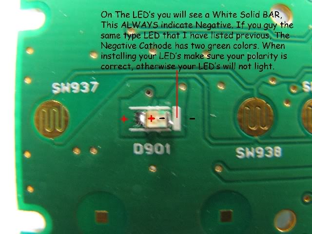
When soldering, you have to remember that patience is key and you must not apply too much heat. If your soldering has a temperature control, set to 800 Degrees, no more and no less. This is the optimal temperature for soldering. When working with the Radio LED's which are really small, I applied a bead of solder to the Negative Solder pad first and then heated up and with tweezers moved the LED into the molten solder, while trying to keep the LED flush with the board. Then I applied Liquid Flux to the Positive solder joint and applied a small bead of solder to my soldering iron and then sldered the Positive side of the LED. Once completed I Heated each side and pressed down, Gently on the LED until completely flush. Your patience will be rewarded, I promise. Practice the samel techniques on all the other lights.
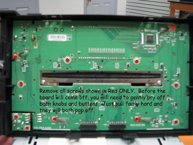
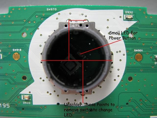
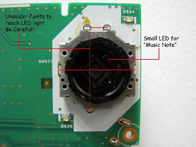
In The Radio, There are two LED's which are hard to get to. You need to desolder the Knobs off the board for the Volume and Tune Knobs. Not too hard to so, just use alot of Liquid Flux, Desoldering Pump, and Braid. Once you get them both off, you can get down to the basics of getting all of the lights replaced. Pics soon to follow.
1.) Solering Iron
2.) Liquid Flux
3.) 60/40 Rosin Core Solder
4.) Small Set of Tweezers
5.) 7mm Socket, with Extension
6.) Phillips Head Screwdriver
7.) Small Flat Head Screwdriver
8.) PLCC-2 LED's - For everything except Radio, Rear Wiper Button)
9.) 1.4mm SMD LED's - For Only Radio, & Rear Wiper Button
10.) 5mm LED - For Overhead LED ONLY
11.) Desoldering Braid
12.) Desoldering Pump
13.) A whole lot of patience and a steady hand.
For the Radio Only & Rear Wiper Button ONLY (0805 - 1.4mm SMD LED):
http://mouser.com/Search/Refine.aspx...PartNumber%7c0
For HVAC, I/P Cluster, 4-Way Flasher Switch, Lock Buttons, & Mirror Switch ONLY (PLCC-2 - LED):
http://www.oznium.com/plcc-2
For Overhead LED ONLY: 5mm LED
http://www.oznium.com/led
I Bought all lights from www.mouser.com and www.oznium.com, which are great sites. Mouser, has the best selection, but may take a while to find the lights you need.
Soldering Instructions/Tips:
When soldering, you have to remember that patience is key and you must not apply too much heat. If your soldering has a temperature control, set to 800 Degrees, no more and no less. This is the optimal temperature for soldering. When working with the Radio LED's which are really small, I applied a bead of solder to the Negative Solder pad first and then heated up and with tweezers moved the LED into the molten solder, while trying to keep the LED flush with the board. Then I applied Liquid Flux to the Positive solder joint and applied a small bead of solder to my soldering iron and then sldered the Positive side of the LED. Once completed I Heated each side and pressed down, Gently on the LED until completely flush. Your patience will be rewarded, I promise. Practice the samel techniques on all the other lights.
In The Radio, There are two LED's which are hard to get to. You need to desolder the Knobs off the board for the Volume and Tune Knobs. Not too hard to so, just use alot of Liquid Flux, Desoldering Pump, and Braid. Once you get them both off, you can get down to the basics of getting all of the lights replaced. Pics soon to follow.
Last edited by NxlKing2304; 03-01-2009 at 02:26 PM.
03-01-2009, 12:44 PM
#3
Senior Member
Thread Starter
Join Date: 02-09-2009
Location: New Jersey
Posts: 296
Removal Instructions:
Removal Instructions:
Radio & HVAC Controls:
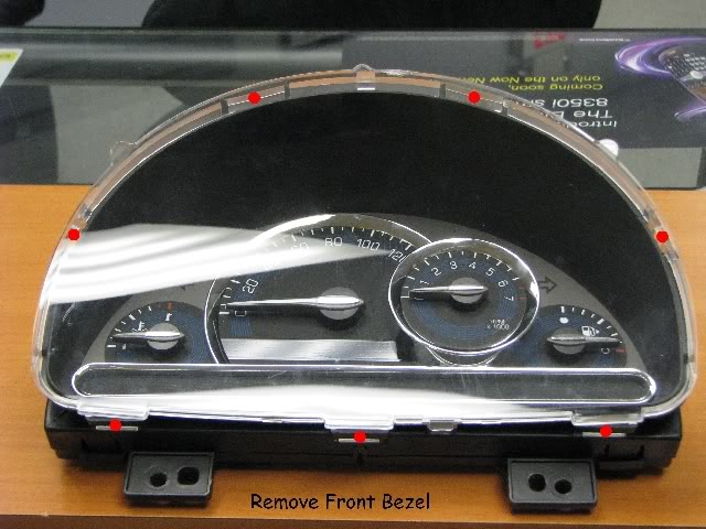
1.) Remove Power Window Switch/Bezel & Chrome Trim. Move to the side.
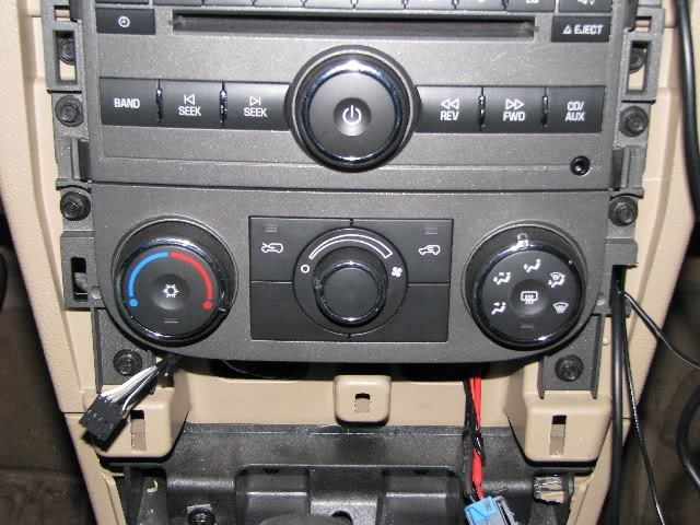
2.) Remove HVAC Controls by taking out four 7mm Hex Screws from the unit (Figure 1). There are three connectors on the back to disconnect. Put this aside for later.
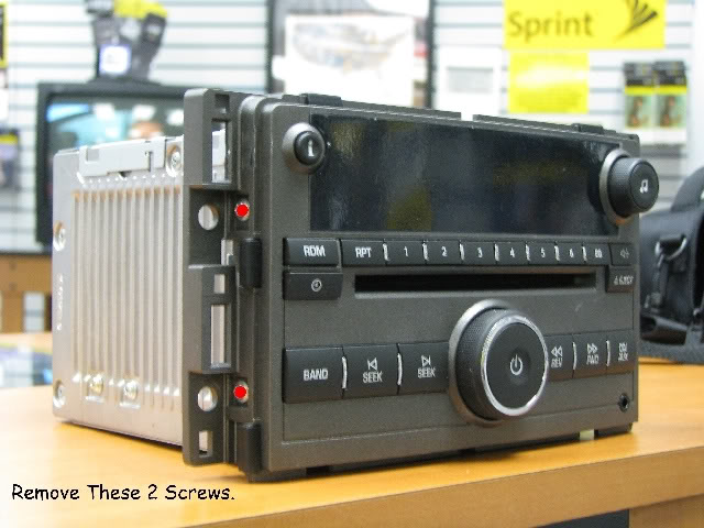
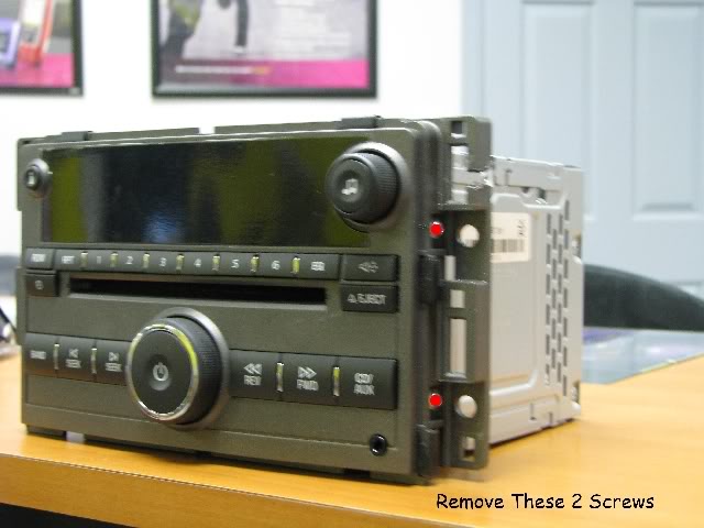
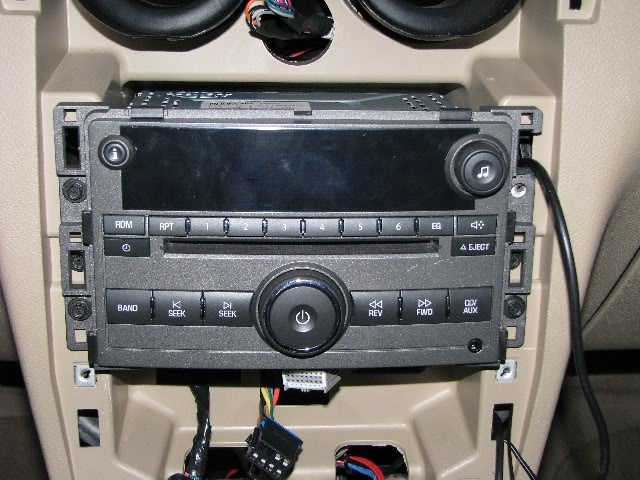
3.) Remove Radio by taking out four 7mm Hex Screws from the unit (Figure 2). There are two connectors on the back to disconnect & the antenna wire to disconnect. Put this aside for later.
Steering Wheel Buttons:
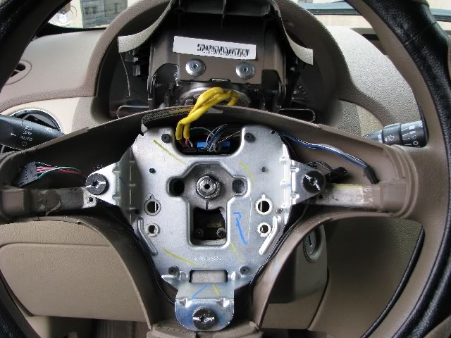
1.) Disconnect Airbag Fuse in Passenger side fuse block. It�s the Red 10A. Take a small Allen Key and press in and towards you on both sides of the airbag. There are small holes on the backside of the steering wheel. You may want to open your hood and remove the Horn Relay so you don�t piss off your neighbors. Airbag will pull straight towards you once both springs have been disengaged. Pull the yellow wires gently away from horn switch and put airbag on top of steering wheel (Figure3).
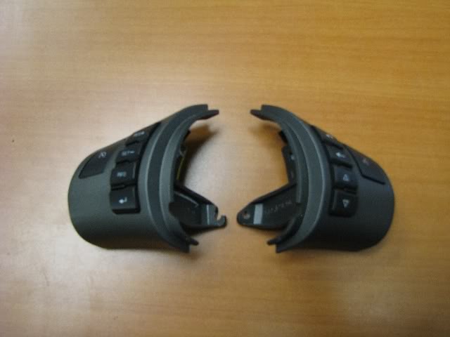
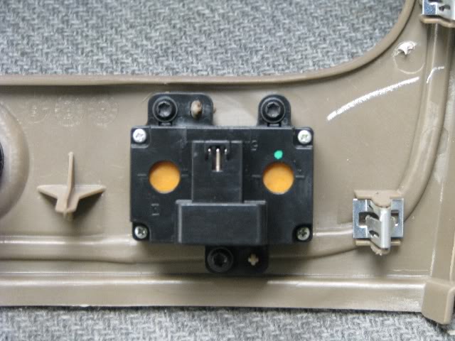
2.) Remove both screws which hold on the left and right hand side controls. Disconnect both switches and remove them (Figure4). Set these aside for later.
I/P Cluster:
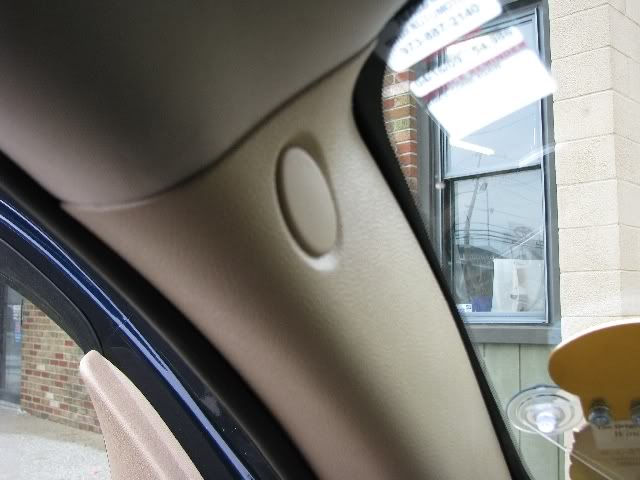
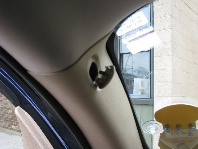
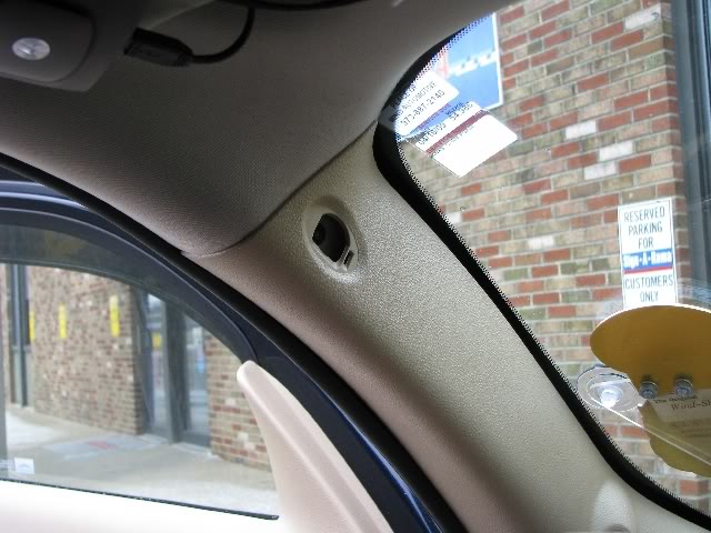
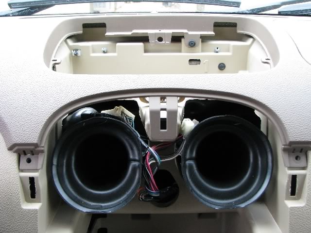
1.) Remove Left Pillar Mount. Remove Cover, Screw, and Tweeter harness. Set aside.(Figure5-7)
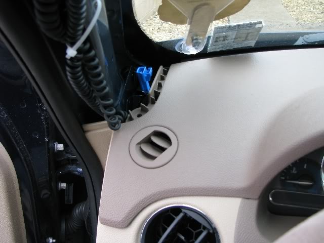
2.) Remove the 7mm Hex Screw. You will be lifting the top portion of the dash board for easier removal of the Cluster. You�ll thank me later by taking a few more minutes. This is a lot easier. (Figure8)
3.) Remove Center two 7mm hex screws on the left and right hand side of the air ducts. Remove Center Storage Bin, by remove two Phillips head screws while open. Lift out and loosen other screw at the back by the defroster duct. Set Aside. (Figure9)
4.) Remove Upper Cluster Bezel by removing two screws. Set aside. (Figure11)
5.) Remove Upper Column Bezel, which snaps off as you pull up. This will give you better access to the next step (Figure12)
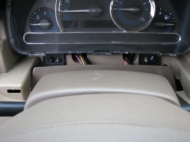
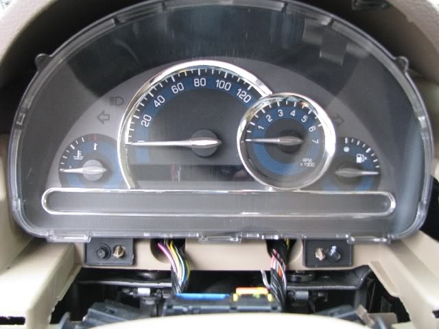
6.) Remove two 7mm hex screws which hold the I/P Cluster in place. Try not to drop them, because it�s a pain to find them. Pull from top of cluster down towards the floor to release. To remove the harness use a flat head screwdriver and press in front of the grey art and push the grey part to the left and forward to complete release.(Figure13)
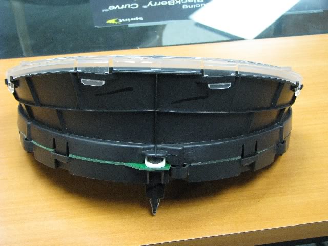
7.) Remove topmost plastic cover by pushing in the lips from the top to the side and then the bottom. (Figure14)
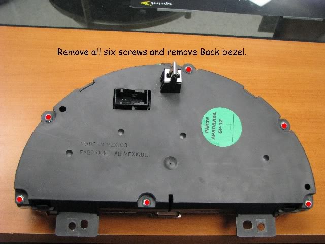
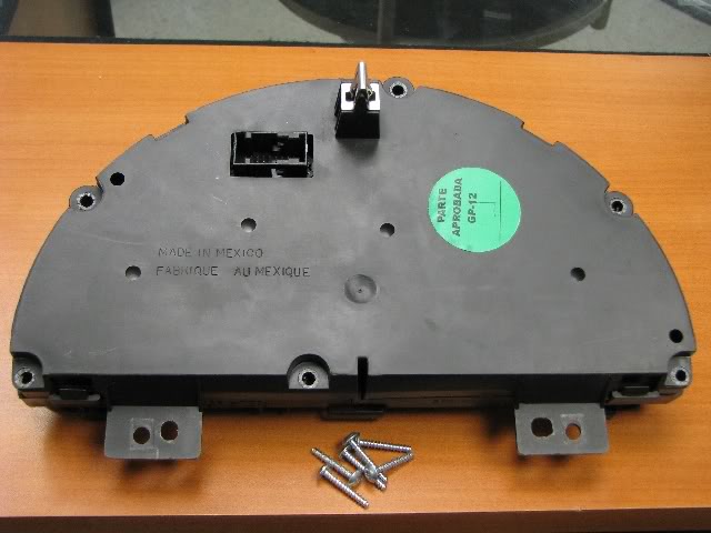
8.) Turn upside down and remove the six Torx screws which hold on the board. Separate the parts, (Figure 15)
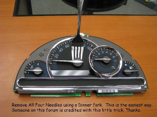
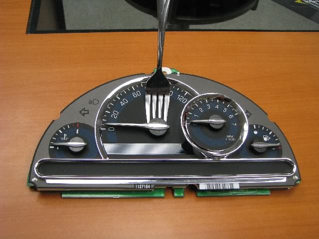
9.) Remove all four needles. The easiest way I found is to use a fork, as another member had indicates on a separate thread on this board. Great tip. Use picture for reference. Gently pry up to release needle. Set Board aside. (Figure16)
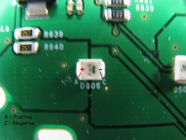
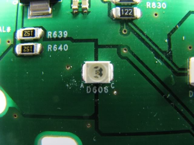
10.) Picture of LED. For your reference all LEDs on this board are labeled by number and have �A� & �C� printed on the board. A = Positive & C = Negative. (Figure17)
Rear Wiper Button:
1.) Remove the four Phillips head screws and remove top cover. (Figure18)
2.) Remove Board from bezel. Set aside. (Figure19)
Radio & HVAC Controls:
1.) Remove Power Window Switch/Bezel & Chrome Trim. Move to the side.
2.) Remove HVAC Controls by taking out four 7mm Hex Screws from the unit (Figure 1). There are three connectors on the back to disconnect. Put this aside for later.
3.) Remove Radio by taking out four 7mm Hex Screws from the unit (Figure 2). There are two connectors on the back to disconnect & the antenna wire to disconnect. Put this aside for later.
Steering Wheel Buttons:
1.) Disconnect Airbag Fuse in Passenger side fuse block. It�s the Red 10A. Take a small Allen Key and press in and towards you on both sides of the airbag. There are small holes on the backside of the steering wheel. You may want to open your hood and remove the Horn Relay so you don�t piss off your neighbors. Airbag will pull straight towards you once both springs have been disengaged. Pull the yellow wires gently away from horn switch and put airbag on top of steering wheel (Figure3).
2.) Remove both screws which hold on the left and right hand side controls. Disconnect both switches and remove them (Figure4). Set these aside for later.
I/P Cluster:
1.) Remove Left Pillar Mount. Remove Cover, Screw, and Tweeter harness. Set aside.(Figure5-7)
2.) Remove the 7mm Hex Screw. You will be lifting the top portion of the dash board for easier removal of the Cluster. You�ll thank me later by taking a few more minutes. This is a lot easier. (Figure8)
3.) Remove Center two 7mm hex screws on the left and right hand side of the air ducts. Remove Center Storage Bin, by remove two Phillips head screws while open. Lift out and loosen other screw at the back by the defroster duct. Set Aside. (Figure9)
4.) Remove Upper Cluster Bezel by removing two screws. Set aside. (Figure11)
5.) Remove Upper Column Bezel, which snaps off as you pull up. This will give you better access to the next step (Figure12)
6.) Remove two 7mm hex screws which hold the I/P Cluster in place. Try not to drop them, because it�s a pain to find them. Pull from top of cluster down towards the floor to release. To remove the harness use a flat head screwdriver and press in front of the grey art and push the grey part to the left and forward to complete release.(Figure13)
7.) Remove topmost plastic cover by pushing in the lips from the top to the side and then the bottom. (Figure14)
8.) Turn upside down and remove the six Torx screws which hold on the board. Separate the parts, (Figure 15)
9.) Remove all four needles. The easiest way I found is to use a fork, as another member had indicates on a separate thread on this board. Great tip. Use picture for reference. Gently pry up to release needle. Set Board aside. (Figure16)
10.) Picture of LED. For your reference all LEDs on this board are labeled by number and have �A� & �C� printed on the board. A = Positive & C = Negative. (Figure17)
Rear Wiper Button:
1.) Remove the four Phillips head screws and remove top cover. (Figure18)
2.) Remove Board from bezel. Set aside. (Figure19)
Last edited by NxlKing2304; 03-01-2009 at 01:16 PM.
 03-01-2009, 12:47 PM
#8
Senior Member
Thread Starter
Join Date: 02-09-2009
Location: New Jersey
Posts: 296
LED Locations
LED Locations:
I/P Cluster: (A=Pos, C=Neg)
D801 Water Temp Needle Color
D802 Speedometer Needle Color
D803 Tachometer Needle Color
D804 Fuel Needle Color
D806 Water Temp Gauge Color
D807 Speedometer Gauge Color
D808 Speedometer Gauge Color
D809 Speedometer Gauge Color
D810 Tachometer Gauge Color
D811 Tachometer Gauge Color
D812 Tachometer Gauge Color
D813 Fuel Gauge Color
D815 kM/h Light
D816 Mph Light
D610 High Beam Indicator Light
D601 High Beam Indicator Light
D506 Left Blinker Indicator Light
D505 Right Blinker Indicator Light
I/P Cluster - Bottom Row:
D506 Security Warning Light
D507 Battery Warning Light
D509 Oil Warning Light
D508 Water Temp Warning Light
D503 Parking Brake Warning Light
D605 Check Engine Warning Light
D602 Fog Lamp Indicator Light
D607 None
D608 None
D604 Up-Shift Warning Light - (If Manual Transmission)
D501 Air Bag Warning Light
D504 Seatbelt Warning Light
D502 ABS System Warning Light
D510 Tire Pressure Light - (If Equipped)
D512 None
D511 Traction Control Indicator Light - (If Equipped)
HVAC Controls:
LD1 A/C On Light
LD11 Recirc Air On Light
LD13 Heated Seat High/Low Setting On Light - Passenger Side
LD14 Heated Seat High/Low Setting On Light - Passenger Side
LD15 Heated Seat High/Low Setting On Light - Drivers Side
LD16 Heated Seat High/Low Setting On Light - Drivers Side
LD17 Fresh Air On Light
LD18 Hot Temperatue Light
LD19 Hot Temperature Light
LD20 Cold Temperatue Light
LD21 Cold Temperature Light
LD22 Temperature Knob Light
LD23 Temperature Knob Light
LD24 Temperature Knob Light
LD25 Fresh Air Light
LD26 Heated Seat Light - Drivers Side
LD27 Recirc Air Light
LD28 Heated Seat Light - Passenger Side
LD29 Fan Speed Knob Light
LD30 Fan Speed Knob Light
LD31 Fan Speed Knob Light
LD32 Mode Selection Knob Light
LD35 Mode Selection Knob Light
LD36 Mode Selection Knob Light
Rear Washer Button:
LED1 Rear Wiper Left Button
LED2 Rear Wiper Right Button
LED3 Rear Wiper Center Button
Steering Wheel Controls:
No Markings - Lights Are Self-Explanatory
Last edited by NxlKing2304; 03-01-2009 at 03:21 PM.