


Installing an Oil Catch Can


Senior Member
Joined: 09-02-2010
Posts: 383
From: Philadelphia, PA
Here is what I did months ago before I found what you guy's were working on. I drilled the bottom of the manifold, because it was thicker there. Funny thing is I had the engine tore apart so long before I did this I forgot about the fuel rail, then I found what you guy's are working on and thought I made an idiot move where I placed my outlet. Looking closer I think it will work. BY CHAnCE ONLY!! I hate to say that. But I'm not perfect. Lol. I will show pictures of it on head tomorrow.
Attachment 18717
here is what I have and it does clear with a couple of modification. very easy.
Attachment 18747
Attachment 18750
Attachment 18717
here is what I have and it does clear with a couple of modification. very easy.
Attachment 18747
Attachment 18750


Moderator
Joined: 05-01-2014
Posts: 8,512
From: California
The potential downsides to locating the port under the manifold, that I can think of, are -
1. It may be very difficult to get to if you need to.
2. The oil could puddle in the low point of the line, possibly clogging the line.
1. It may be very difficult to get to if you need to.
2. The oil could puddle in the low point of the line, possibly clogging the line.

Thread Starter
Senior Member
Joined: 05-29-2015
Posts: 542
From: Cleveland, OH
I agree RJ, it seems power mizer got lucky and cleared the fuel rail some how. I wouldn't want the headache of trying to reach it either. Hopefully he won't need to often.
Finally got everything laid out to start building my catch cans. These are a modular, 3 chamber design. Dirty tank, filtering chamber, and fresh air chamber. Made from quality 6061 aluminum and Stainless steel guts. Sorry I don't have a better drawing, I'll keep updated with the progress. Should have enough material for 6 cans or so.
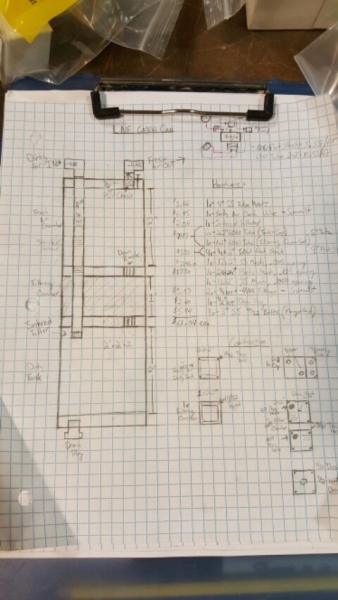
Dirty air enters and goes straight through a SS tube into the dirty tank. Exits through a sintered filter and must work its way out through the filter chamber before it can exit as clean air. With a built in pcv check (hopefully, in theory...)
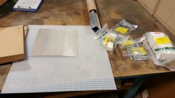
Here's how the material started. 6' each of 6061 aluminum, 2" square tube and 2" flat stock. SS wire mesh with .015" and .050" openings. To separate those I'll be using the large sheet of poly filtering material. The filtering chamber is made up of layers of poly and SS mesh.
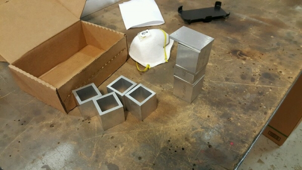
Here's the rough cut, basic shape. 6" tall, Dirty tank and fresh air chamber are 2"T, filtering chamber is 1"T. There's a 1" overhang on the lid for mounting purposes.
The wife's SS is finally coming back together and I'll need a pair of these to get it running again. There's also a local SS owner who would like to try them out. Hope to be "finished" sometime next week. Lot of machining yet to do.
Finally got everything laid out to start building my catch cans. These are a modular, 3 chamber design. Dirty tank, filtering chamber, and fresh air chamber. Made from quality 6061 aluminum and Stainless steel guts. Sorry I don't have a better drawing, I'll keep updated with the progress. Should have enough material for 6 cans or so.
Dirty air enters and goes straight through a SS tube into the dirty tank. Exits through a sintered filter and must work its way out through the filter chamber before it can exit as clean air. With a built in pcv check (hopefully, in theory...)
Here's how the material started. 6' each of 6061 aluminum, 2" square tube and 2" flat stock. SS wire mesh with .015" and .050" openings. To separate those I'll be using the large sheet of poly filtering material. The filtering chamber is made up of layers of poly and SS mesh.
Here's the rough cut, basic shape. 6" tall, Dirty tank and fresh air chamber are 2"T, filtering chamber is 1"T. There's a 1" overhang on the lid for mounting purposes.
The wife's SS is finally coming back together and I'll need a pair of these to get it running again. There's also a local SS owner who would like to try them out. Hope to be "finished" sometime next week. Lot of machining yet to do.

Moderator
Joined: 05-01-2014
Posts: 8,512
From: California
I reached the miles for the end of phase 2 testing, with unexpected results.
I only caught about 1 oz. However, it looks like oil was blowing out the oil filler cap also(yeah, I know, not good). I see 2 potential causes:
1. Port 2 just isn't able to evacuate the crankcase pressure.
2. The hose between the brake booster line and the Tee between the catch can and turbo may have worked loose at said Tee. See pic, blue arrow.
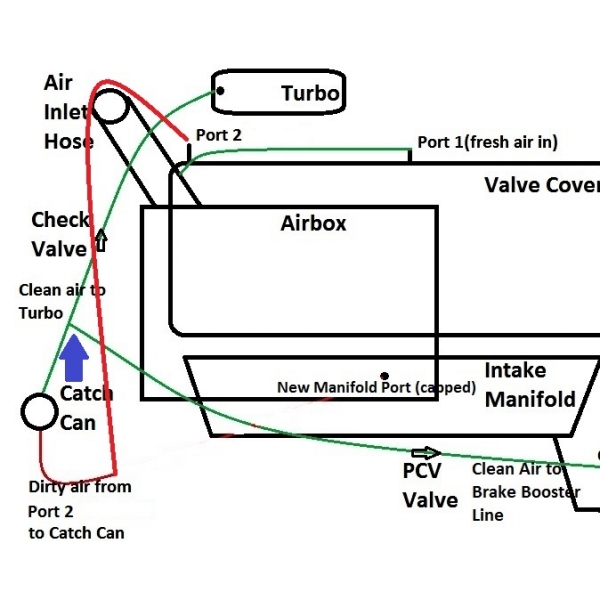
When I moved the hose for access to remove the cap on the new intake port, the hose popped right off the Tee. There is no evidence of oil leaking at that spot, but it would have been a vacuum leak, not necessarily an oil leak. I know, that's clean side anyway, but there was mixed liquids there inside the Tee, so my catch can is allowing some vapors by the filtration media(that's a battle for another day).
It's a poor connection to the Tee, I'm going to rework it with a different Tee.
So the (possibly)loose hose may have leaked enough vacuum that the crankcase pressure could not evacuate very well, or port 2 can't evacuate on it's own. I may repeat phase 2 at another time, but now it's on to phase 3.
I only caught about 1 oz. However, it looks like oil was blowing out the oil filler cap also(yeah, I know, not good). I see 2 potential causes:
1. Port 2 just isn't able to evacuate the crankcase pressure.
2. The hose between the brake booster line and the Tee between the catch can and turbo may have worked loose at said Tee. See pic, blue arrow.
When I moved the hose for access to remove the cap on the new intake port, the hose popped right off the Tee. There is no evidence of oil leaking at that spot, but it would have been a vacuum leak, not necessarily an oil leak. I know, that's clean side anyway, but there was mixed liquids there inside the Tee, so my catch can is allowing some vapors by the filtration media(that's a battle for another day).
It's a poor connection to the Tee, I'm going to rework it with a different Tee.
So the (possibly)loose hose may have leaked enough vacuum that the crankcase pressure could not evacuate very well, or port 2 can't evacuate on it's own. I may repeat phase 2 at another time, but now it's on to phase 3.
Moderator
Joined: 05-01-2014
Posts: 8,512
From: California
I couldn't find a tee that was 5/16" barb on the run and 1/2" barb at the tee, so I had to make one. Thankfully, I had a 1/4" MNPT x 1/2" barb, and a 1/4" MNPT x 5/16" barb left over from my small catch cans. I also had (2) $5 coupons for ACE hardware, so I got what I needed for under $2. Here it is assembled.
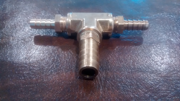
Installed it in about 2 minutes, so I should be good to go now!
Installed it in about 2 minutes, so I should be good to go now!
Moderator
Joined: 05-01-2014
Posts: 8,512
From: California
OK so phase 2 and 3 are both a bust. I'm still blowing oil out through the oil filler cap, so 1 vapor draw point is simply not enough to evacuate the crankcase pressure!
I'm going to have to tee the 2 original vapor draw points together, like drummerboy0088 has done, and start testing again.
I'm going to have to tee the 2 original vapor draw points together, like drummerboy0088 has done, and start testing again.

Moderator
Joined: 01-23-2009
Posts: 26,533
From: Fredericksburg,VA